background image

SMC Smoke Detector Guide 

 Copyright 

©

2011 SMC Networks


Page 3 


All Rights Reserved 


I/M SMCSMXX-Z rev. 2.0 

7/26/11 

6   

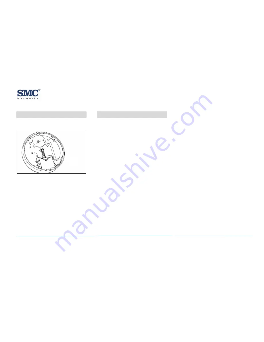
Installing Batteries 

A. 

Slide the battery compartment cover away 

from the smoke detector to unsnap it and 
lift it off. 


B. 

Observing proper polarity, insert two 3V 
lithium batteries into the smoke detector 

battery compartment and replace the 
battery compartment cover. 

C. 

Remove the red plastic dust cover from the 

smoke detector. The smoke detector ships 
with a dust cover for protection on 
construction sites with dusty environments. 


7   

Adding to the TouchScreen 


A.

Log in to the Settings app with an Installer 

code.  

B. 

In the Settings menu, tap Sensors & Zones > 
Add a Sensor/Zone

C. 

Place the smoke detector in Search mode 

and prepare it to be added to the 
TouchScreen (refer to the installation 

documentation for your sensors). Available 
sensors meet the following requirements: 

Defaulted 

Not currently paired with another 
TouchScreen device 

Currently in Search mode 

D. 

At the Locating Wireless Sensors screen, tap 
Next. A Done button appears on the screen 

and the TouchScreen searches for sensors 
that are available to be added. As sensors 

are found, a grayed icon appears for that 
sensor. 

E. 

Fault each found sensor to pair it to the 

TouchScreen. The icon for each sensor is 
undarkened as it is faulted and the 

TouchScreen beeps. The sensor is paired to 
the TouchScreen. 

F. 

When all the sensors are found and paired, 

tap Stop. Any located sensors that were not 
paired are released by the TouchScreen a

can be added later. The Wireless Sens

nd 

ors 


M. 

ew its details. 

Change the details as needed or tap Next to 

cycle through all the sensors. The sensors 
are marked as configured.

continued on next page

Located screen shows the number of 
wireless sensors found and paired. 
Tap Next. The Con

G. 

figure Wireless Sensors 

screen shows icons of the sensors that were 
found and paired. 
Touch each sensor icon 

H.

to configure the 

corresponding device. The Add Sensor/Zone 
Modify screen appears. 
To change the Smoke Icon (if multiple 

I. 

options are available) and the 24-Hour F
zone function, tap the currently selecte

value. 

ire 

J. 

Tap Next. The Add Sensor/Zone Modify 
screen appears. 
To modify a text field on the TouchScreen, 
tap the field, u

K. 

se the onscreen keyboard to 

enter your changes, and tap Done to save 

your changes. 

L. 

When all sensors are configured properly, 
tap Next in the Configure Wireless Sensors 

screen. 
If all of the sensors have not been 
configured, the Modify screen appears for 

each sensor to let you revi

Battery 
Compartment 

Summary of Contents for SMCSM01-Z

Page 1: ...ed in all common areas and work spaces such as corridors lobbies storage rooms equipment rooms and other tenantless spaces in those environments suitable for proper detector operation in accordance with this code NFPA 72 2 1 4 2 3 Selective Coverage Where codes standards laws or authorities having jurisdiction require the protection of selected areas only the specified areas shall be protected in ...

Page 2: ... to protect and their burning characteristics Human occupancy Total area to be monitored Ceiling height and surface condition Air movement and vent locations Obstructions Deflections After considering these factors choose a location Where the temperature range is between 40 and 100 F 4 4 and 37 8 C Where the humidity is between 0 and 90 noncondensing Away from ventilation sources that can prevent ...

Page 3: ... icon appears for that sensor E Fault each found sensor to pair it to the TouchScreen The icon for each sensor is undarkened as it is faulted and the TouchScreen beeps The sensor is paired to the TouchScreen F When all the sensors are found and paired tap Stop Any located sensors that were not paired are released by the TouchScreen a can be added later The Wireless Sens nd ors M ew its details Cha...

Page 4: ...led D Test communications between the control panel and smoke detector again Press the Test button on the alarm for 8 to 10 seconds The smoke detector sends a signal to the control panel Verify that the signal at the control panel was received E Test the smoke detector see section 9 F The control panel alarm and all auxiliary functions should be verified for a complete test of the system 9 Testing...

Page 5: ... security zones appear tap the zone you want to test for connectivity and follow the instructions from the TouchScreen After adding the smoke detector to the TouchScreen and installing the smoke detector test the signal strength between the TouchScreen and its added sensors security zones A Be sure steps A through D in section 6 Adding to the TouchScreen on page 3 have been performed Signal Streng...

Page 6: ...t or use a soft bristled brush to remove dust and dirt from the smoke chamber base G Line up the new smoke chamber with the optical base by aligning the arrows on the smoke chamber to the latches on the optical base and snap down into place H Replace the detector cap by lining up the cap with the smoke detector Then insert the cap into the smoke detector and turn clockwise approximately 15 degrees...

Page 7: ...B Tap the Turn Zone Off button for the smoke detector The Turn Zone Off button changes to Turn Zone On C When the system is disarmed the Security Status header shows that some zones have been bypassed 12 Delete the Smoke Detector Deleting a sensor such as your SMC Smoke Detector from the premises removes it from being monitored by the customer s system This is not the same as disabling bypassing a...

Page 8: ...ase the tamper switch The LED blinks green F Replace the front cover G Replace all the batteries to the smoke detector and the back cover 14 Compliance Statements Model SMCSM01 Z FCC ID JI5 SMCZB01 IC ID 4137A SMCZB01Z Model SMCSM02 Z FCC ID RU4 HWM6505 ZZ IC ID 9682A HWM6505 ZZ Federal Communication Commission Interference Statement This equipment has been tested and found to comply with the limi...

Page 9: ...areils radio exempts de licence Son fonctionnement est sujet aux deux conditions suivantes 1 le dispositif ne doit pas produire de brouillage préjudiciable et 2 ce dispositif doit accepter tout brouillage reçu y compris un brouillage susceptible de provoquer un fonctionnement indésirable IMPORTANT NOTE Radiation Exposure Statement The product complies with the US Canada portable RF exposure limit ...

Reviews: