


- 40 -
Rotary actuator mounting (tapped holes)
3. The mounting face has holes and slots for positioning. If required use them for accurate
positioning of the rotary actuator.
4. If it is necessary to operate the product when it is not energized, use the manual override
screws.
When the product is operated with the manual override screws, check the position of the manual
override of the table, and leave necessary space. Do not apply excessive torque to the manual override
screws that could lead to damage and malfunction of the product.
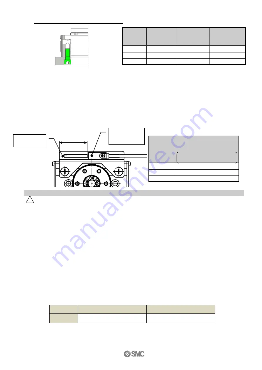
5. The proximity sensor for the return to origin for 360o type can be r/-30
o
.
If the position of the proximity sensor for return to origin is changed, the tightening torque
must be 0.6 +/-0.1
[
Nm
]
6.3 Handling
1. If an external guide is mounted, connect it so that impact and load will not be applied to it.
Use a freely moving connector (such as a coupling).
2. The positioning force should be set to 100% of the the initial value.
If the positioning force is set below the initial value, there may be variation in the cycle time, or an alarm
may be generated.
3. INP output signal
1) Positioning operation
When the product comes within the set range by step data [In position], output signal will be turned
on. Initial value: Set to [0.50] or higher.
2) Pushing operation
When the pushing force exceeds the [TriggerLV] value the INP ( In position) output signal is turned
on.
Please set the [Pushing force] and the [TriggerLV] within the specified range.
a. To ensure that the actuator pushes the workpiece by the inputted [pushing force], it is
recommended that the [TriggerLV] is set to the same value as the [pushing force].
b. When the [TriggerLV] and [pushing force] are set to be less than the lower limit of the specified
range, there is the possibility that the INP output signal will be switched on from the pushing
operation start position.
< Pushing force and trigger LV range >
Model
Set value of pushing force[%]
Set value of TriggerLV[%]
LER*
40~50
40~50
Part no.
Bolt
Max.
tightening
torque [Nm]
Max. thread
depth L[mm]
LER*10
M6×1
5.0
12
LER*30
M8×1.25
12.0
16
LER*50
M10×1.5
25.0
20
Part no.
L[mm]
(Default value)
Cable entry:
Basic type / Entry from the left
Between the sensor holder
end and Proximity sensor end
LER*10-1
31 / 31
LER*30-1
42 / 42
LER*50-1
51.5 / 51.5
! Caution
L
Proximity
sensor
assembly
Sensor
holder
Summary of Contents for LER Series
Page 3: ... 2 7 Troubleshooting 42 ...