


- 22 -
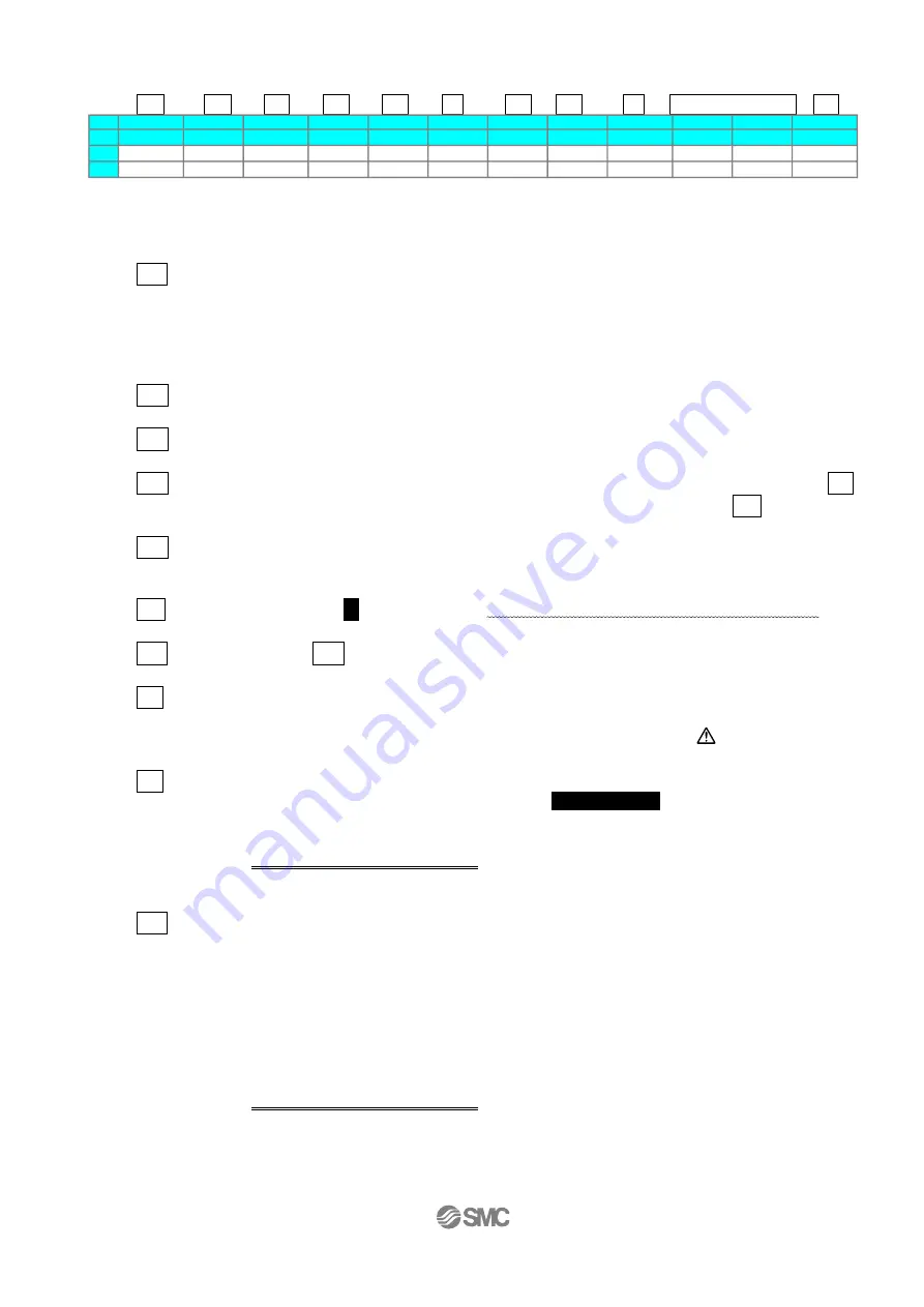
<Items and set values in positioning operation>
Step No. 0: Positioning operation
a b c d e f g h i j k
No.
Move M
Speed
Position
Accel
Decel
PushingF TriggerLV PushingSp
MovingF
Area1
Area2
In pos
°/s
°
°/s^2
°/s^2
%
%
°/s
%
°
°
°
0 ABS
200
0.00
3000
3000
0
0
0
100
20.00
40.00
0.50
1 ABS
200
180.00
3000
3000
50
50
30
100
179.00
181.00
5.00
【
◎
】
Need to be set
・ 【○】
Need to be adjusted as required
【
X
】
Not used. Items don't need to be changed in positioning operation.
a
<
◎
Movement MOD>
When the absolute position is required, set Absolute
When the relative position is required, set Relative
⇒
Absolute: Distance from the origin position. / General setting method
Relative: Feed from the current position. / This is used when simplified data.
b
<
◎
Speed>
Transfer speed to the target position.
c
<
◎
Position>
Target position.
d
<
○
Acceleration>
The parameter which defines how rapidly the actuator reaches the speed set in
b
The higher the set value, the faster it it reaches the speed set in
b
.
e
<
○
Deceleration>
The parameter which defines how rapidly the actuator comes to stop.
The higher the set value, the quicker it stops.
f
<
◎
Pushing force>
Set
0
.
(
If values other than 0 set, the operation will be changed to the pushing operation.
)
g
<X Trigger LV>
h
<X Pushing speed>
i
<
○
Moving force>
Max. force at the positioning operation.
The force is automatically adjusted corresponding to the load.
/See 6.3
Caution
(2) on p. 40
j
<
○
Area1
,
Area2>
This is the condition that turns on the AREA output signal.
The setting condition should be
Area 1<Area 2
.
It is possible to set at Relative operation too.
The position will be Absolute (position from the origin).
Example
)
In case of Step no.0
【
AREA
】
output signal is outputted between Area 1:20 and Area 2:40.
k
<
○
In position> This is the condition that turns on the INP (in position) output signal.
⇒
When the electric rotary actuator reaches the range of the target position, the
INP output signal is output.
When the electric actuator enters the range of [in position], the INP output signal
turns on.
When it is necessary to output the target position reaching signal earlier, make
the value larger.
Note) Default
:
Set the value more than
【
0.50
】
.
Example
)
In case of Step no.0
Position
:
0 + In position
:
0.5
=
【
INP
】
is outputted from the value of 0.5.
Summary of Contents for LER Series
Page 3: ... 2 7 Troubleshooting 42 ...