


-
20
-
No.JXC
※
-OMU0030-A
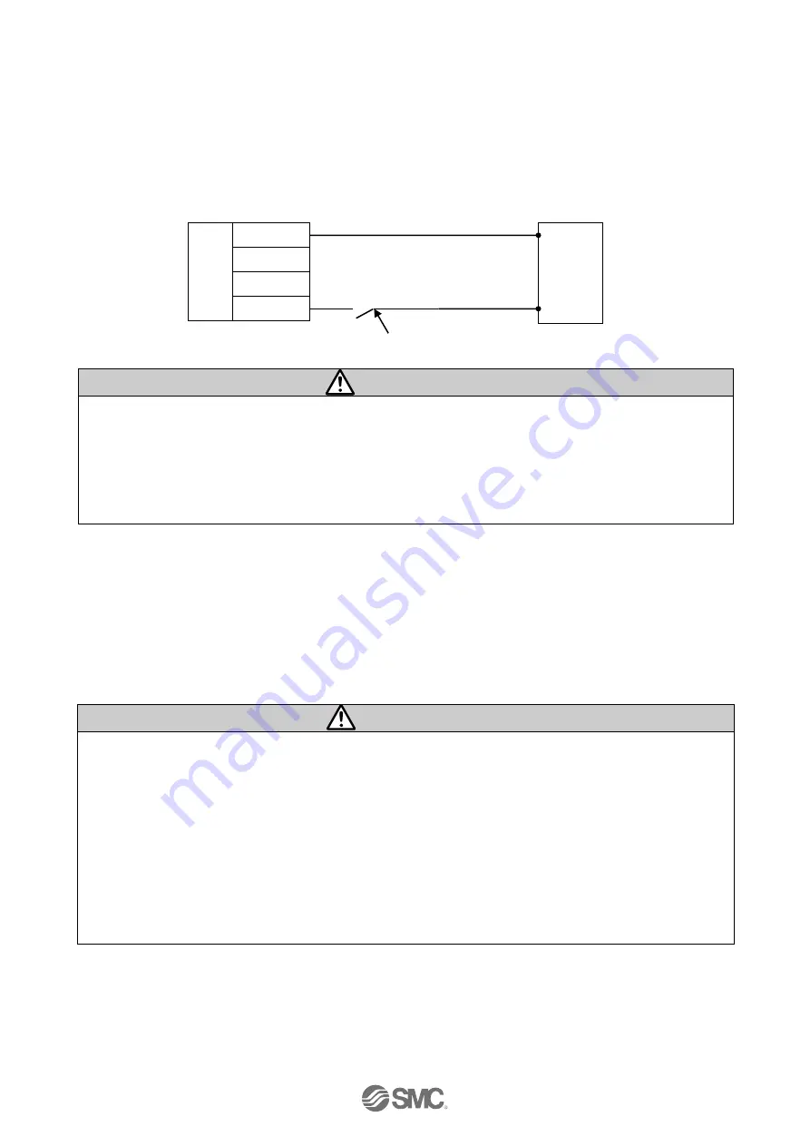
(2) Wiring of the lock release
Install an unlocking switch for adjustment or recovery during an emergency of the electric actuator with
lock. The switch (24 VDC, Contact capacity: 0.5A or more) should be obtained separately.
One terminal of the lock release switch should be connected to the 24 VDC power supply and the
other should be connected to the BK RLS terminal. When this is switched on, the lock will be released
forcibly.
Power supply cable Controller input power supply
Switch for forced unlocking
Caution
If the electric actuator is a non-lock type, it is not necessary to wire the BK RLS terminal.
Do not supply power to the BK RLS (lock release) during normal operation.
The 24 VDC supply to the BK RLS (lock release) is only required for the adjustment and the recovery
in the emergency.
- STOP command (CN4 14pin STOP) is turned ON and Servo is turned OFF.
- When the control power supply (C24V) is shut off.
(3) Stop the power supply for the motor
If it is necessary to shut off the power supply for the motor from outside, connect the relay between the
input power supply for the controller 24 VDC and the power supply plug for the controller M24V.
(Refer to the wiring diagram in the next page.)
The motor power supply should be shut off after the STOP command (CN4 14pin STOP) is turned ON.
Refer to
“6.3 Details of parallel input / output signal and cable”
for the STOP command
Warning
- Do not perform a return to origin position when the the power supply for the motor (M24V) is off. The
controller cannot recognize the correct origin if a return to origin instruction is made with the motor
drive power (M24V) disconnected.
- If the M24V is off during electric actuator operation, there will be an additional delay experienced
before it stops (the stop distance will be extended) due to inertia of the work piece or regenerated
energy. When the M24V is turned off, and the STOP command is turned ON (CN4 14pin STOP)
simultaneously the time to stop can be shortened.
- If the motor drive power is off during a vertical stop, the table may drop due to lock response.
- BK RLS is internally connected to the M24V inside the controller, so do not apply 24 VDC to the BK
RLS terminal when the M24V is off.
0V
M24V
C24V
BK RLS
0V
24V