ALC700 SERIES
(ALC704/ALC708)
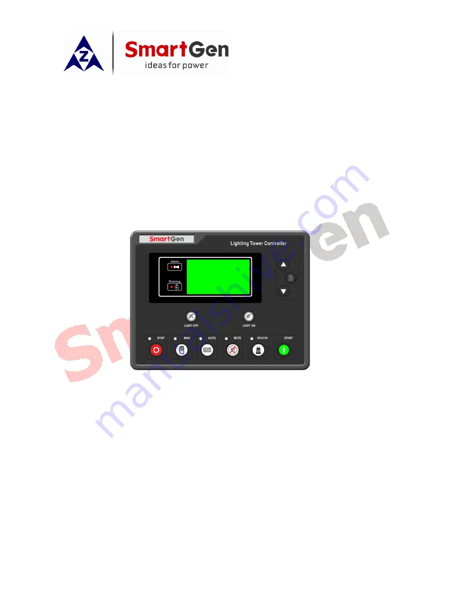
LIGHTING TOWER CONTROLLER
USER MANUAL
ZHENGZHOU SMARTGEN TECHNOLOGY CO.,LTD
Page 1: ...ALC700 SERIES ALC704 ALC708 LIGHTING TOWER CONTROLLER USER MANUAL ZHENGZHOU SMARTGEN TECHNOLOGY CO LTD ...
Page 2: ...written permission of the copyright holder Applications for the copyright holder s written permission to reproduce any part of this publication should be addressed to SmartGen Technology at the address above Any reference to trademarked product names used within this publication is owned by their respective companies SmartGen Technology reserves the right to change the contents of this document wi...
Page 3: ... Symbols description Symbol Instruction NOTE Highlights an essential element of a procedure to ensure correctness CAUTION Indicates a procedure or practice which if not strictly observed could result in damage or destruction of equipment WARNING Indicates a procedure or practice which could result in injury to personnel or loss of life if not followed correctly ...
Page 4: ... 6 2 SHUTDOWN ALARMS 27 6 3 TRIP AND STOP ALARMS 29 7 WIRING CONNECTION 30 8 SCOPES AND DEFINITIONS OF PROGRAMMABLE PARAMETERS 33 8 1 CONTENTS AND SCOPES OF PARAMETERS 33 8 2 ENABLE DEFINITION OF PROGRAMMABLE OUTPUT PORT 1 4 36 8 3 ENABLE DEFINITION OF PROGRAMMABLE INPUT PORT 1 4 39 8 4 ENABLE DEFINITION CONTENTS 39 8 5 SENSOR SELECTION 40 8 6 SENSORS SETTING 41 8 7 OVER CURRENT ACTION 42 8 8 COND...
Page 5: ...ontroller 2018 03 02 Version 1 4 Page 5 of 51 13 INSTALLATION 49 13 1 BATTERY VOLTAGE INPUT 49 13 2 SPEED SENSOR INPUT 49 13 3 OUTPUT AND EXPAND RELAYS 50 13 4 AC INPUT 50 13 5 DC CURRENT INPUT 50 13 6 WITHSTAND VOLTAGE TEST 50 14 FAULT FINDING 51 15 WHOLE SET OF PRODUCT 51 ...
Page 6: ...nctions ALC700 series controllers adopt micro processor technology and combine automation control function with flashlights control function into one product They have LCD display selectable Chinese English languages interface modular design compact structure and simple connections They can be widely used in all types of automatic light tower set with compact structure advanced circuits and high r...
Page 7: ...wer Detection Real time clock and real time calendar functions allow scheduled start stop everyday sunrise and sunset start stop light tower set moreover scheduled start time running duration time sunrise time and sunset time can be set by users as their wish SMS message function GSM modem must be fitted When failure occurs controller will send short messages automatically to max 5 telephone numbe...
Page 8: ...ller can control up to 8 flashlights and the feedback indicator were be fitted on the panel In addition the turn on interval time between two lights can be set by users 99 pieces of event logs can be circularly stored and inquired on the spot also can be print or be inquired via PC More kinds of curves of temperature oil pressure fuel level can be used directly and users can select User Configured...
Page 9: ...er supply output Configurable Relay Output 3 8A DC28V power supply output Configurable Relay Output 4 8A AC250V free volt output Light Control Relay Output 1 4 8A AC250V free volt output total output current 8A If 1 4 is all used the maximum current of each light is 2A Light Control Relay Output 5 8 8A AC250V free volt output total output current 8A If 1 4 is all used the maximum current of each l...
Page 10: ... If alarm occurs again in mute status the controller will remove mute status automatically Flashlight Can control flashlight to switch on or off Start Start lighting tower set in Manual mode Light Off During normal running in manual mode turn off one light for each pressing Press this key for a long time can turn off the light in proper sequence according to preset time Light On During normal runn...
Page 11: ...tton The screen display generator fuel level engine temperature oil pressure flexible sensor information There is no sensor information when flexible sensor select Not used or Digital closed or Digital open The screen display when sensor is open circuit Press button The screen display battery voltage charger voltage engine speed and current time the number in the parentheses is week information FU...
Page 12: ...nergy accumulated run time HH MM SS Press button The screen display load current total active power total apparent power total reactive power and power factor The screen display voltage current and power when DC current is fitted NOTE Pressing can scroll screen circularly GENERATOR STARTS 88888 times HOURS RUN 009999 05 30 ENERGY 0003561 6 kWh LOAD CURRENT 500 500 500 A POWER 330kW 330kVA Cosφ 1 0...
Page 13: ... set begin cranking and flashlight is twinkling if configured Stop delay time will be displayed on the first line Fig 4 C If generator voltage and frequency has reached on load requirements Voltage on load voltage and frequency on load frequency all the lights will illuminate in proper order and the illumination interval delay is 2s can be set as 1 300s Fig 5 6 Fig 1 AUTO TIMER MODE START TIME 16 ...
Page 14: ... will off in proper order and the extinguishing interval delay can be set as 1s 300s The light tower set begin stopping when all the lights off Picture 7 8 NOTE The auto timer mode will be canceled automatically when select other auto start mode STOP DELAY 09 06 02 START TIME 16 28 00 CURRENT TIME 16 33 58 GENERATOR NORMAL RUNNING Fig 6 Fig 7 STOP DELAY 00 00 00 START TIME 16 28 00 CURRENT TIME 23...
Page 15: ...y Auto Mode Select Fig 1 Press and to select 03 Sunrise Sunset Mode and press or to confirm Fig 2 Press and to select 01 Sunrise Sunset Start and press or to confirm Fig 3 B When there are 10s left from start time controller s current time can be set via utility computer software audible alarm relay is active if configured When start time is up light tower set begin cranking and flashlight is twin...
Page 16: ...ia upper computer software then 1 8 lights will off in proper order and the extinguishing interval delay can be set as 1s 300s The light tower set begin stopping when all the lights off Fig 7 8 NOTE The Sunrise Sunset mode will be canceled automatically when select other auto start mode Fig 5 STOP DELAY 07 25 00 START TIME 17 26 00 CURRENT TIME 17 26 15 2 OUTPUT DELAY 09s STOP DELAY 07 25 00 START...
Page 17: ...lingly on the first line of the second screen Fig 3 C If generator voltage and frequency has reached on load requirements Voltage on load voltage and frequency on load frequency all the lights will illuminate in proper order and the illumination interval delay is 2s can be set as 1 300s Fig 4 5 Fig 1 Fig 2 AUTO DIAL UP MODE WAIT SMS COMMAND CURRENT TIME 12 05 18 GENERATOR AT REST Fig 3 AUTO DIAL U...
Page 18: ...hts will off in proper order and the extinguishing interval delay can be set as 1s 300s The light tower set begin stopping when all the lights off Fig 6 7 NOTE The auto SMS mode will be canceled automatically when select other auto start mode Fig 6 AUTO DIAL UP MODE SMS STOP CURRENT TIME 23 32 18 7 OFF DELAY 09s AUTO TIMER MODE SMS STOP CURRENT TIME 23 33 58 COOLING TIME 29s Fig 7 ...
Page 19: ...ephone number which sends start order message should be set via test software and downloaded into controller C When there are 10s left from start time controller s current time can be set via utility computer software audible alarm relay is active if configured When start time is up light tower set begin cranking and flashlight is twinkling if configured Stop delay will be displayed on the first l...
Page 20: ...tility computer software then 1 8 lights will off in proper order and the extinguishing interval delay can be set as 1s 300s The light tower set begin stopping when all the lights off Fig 7 8 NOTE The auto SMS sunrise sunset mode will be canceled automatically when select other auto start mode Fig 5 STOP TIME 07 25 00 START TIME 17 26 00 CURRENT TIME 17 26 00 2 OUTPUT DELAY 09s STOP TIME 07 25 00 ...
Page 21: ... over and remote start signal is active light tower set begin cranking and flashlight is twinkling if configured Fig 3 4 C If generator voltage and frequency has reached on load requirements Voltage on load voltage and frequency on load frequency all the lights will illuminate in proper order and the illumination interval delay is 2s can be set as 1 300s Fig 5 Fig 4 REMOTE START MODE REMOTE START ...
Page 22: ...stop delay is over 1 8 lights will off in proper order and the extinguishing interval delay can be set as 1s 300s The light tower set begin stopping when all the lights off Fig 6 7 8 Fig 7 REMOTE START MODE WAIT REMOTE START CURRENT TIME 23 32 18 8 OFF REMOTE START MODE WAIT REMOTE START CURRENT TIME 23 33 58 COOLING 29s Fig 8 Fig 6 REMOTE START MODE STOP DELAY 10s CURRENT TIME 23 32 18 GENERATOR ...
Page 23: ...n warming up delay is over in addition generator voltage and frequency has reached on load requirements Voltage on load voltage and frequency on load frequency 1 8 lights will illuminate in proper order by pressing button while off in proper order by pressing button Fig 3 4 MANUAL MODE WAIT MANUAL START CURRENT TIME 12 05 18 GENERATOR AT REST Fig 1 Fig 2 MANUAL MODE MANUAL START CURRENT TIME 12 05...
Page 24: ...rder and the extinguishing interval delay can be set as 1s 300s The light tower set begin stopping when all the lights off Press again during this procedure will lead to all lights off at the same time and ETS status of controller Fig 5 6 Fig 5 MANUAL MODE MANUAL STOP CURRENT TIME 23 32 18 8 OFF MANUAL MODE MANUAL STOP CURRENT TIME 23 33 58 COOLING 29s Fig 6 ...
Page 25: ...l and the corresponding alarm information will be displayed on the LCD 5 Loss of Speed Signal When controller detects the speed is 0 it will send warning signal and the corresponding alarm information will be displayed on the LCD 6 Over Frequency When controller detects the generator frequency is higher than the set value it will send warning signal and the corresponding alarm information will be ...
Page 26: ... When controller detects the battery voltage is higher than the set value it will send warning signal and the corresponding alarm information will be displayed on the LCD 17 Flexible Sensor Low When controller detects the sensor value is lower than the minimum set value it will send warning signal and the corresponding alarm information will be displayed on the LCD If the sensor name is configured...
Page 27: ...responding alarm information will be displayed on the LCD 6 Loss of Speed Signal When controller detects the generator speed is 0 it will send a shutdown signal and the corresponding alarm information will be displayed on the LCD 7 Over Frequency When controller detects the generator frequency is higher than the set value it will send a shutdown signal and the corresponding alarm information will ...
Page 28: ...e LCD If the sensor name is configured by users as xxx then xxx open will be displayed on the LCD 17 Flexible Sensor High When controller detects the sensor value is higher than the maximum set value it will send shutdown signal and the corresponding alarm information will be displayed on the LCD If the sensor name is configured by users as xxx then xxx high will be displayed on the LCD 18 Flexibl...
Page 29: ...When controller detects the current is higher than the set value it will send a trip and stop signal and the corresponding alarm information will be displayed on the LCD 2 Aux input 1 4 User defined When the controller detects auxiliary input ports 1 4 trip alarms it will send a trip and stop alarm signal and the corresponding alarm information will be displayed on the LCD If the input port name i...
Page 30: ...h DC voltage via emergency stop button Max 30A fuse is recommended 4 Fuel relay 1 5 mm2 DC voltage is supplied by 3 point rated 8A 5 Start Relay 1 5 mm2 DC voltage is supplied by 3 point rated 8A 6 Aux output 1 1 5 mm2 B output rated 8A 7 Aux output 2 1 5 mm2 8 Aux output 3 1 5 mm2 9 Charger D 1 0 mm2 Connected with charger s D WL terminals Ground connection is not allowed 10 Aux output 4 1 5 mm2 ...
Page 31: ...0 mm2 Connected to N wire of light tower set 29 Sensor COM 1 0 mm2 Public terminal of sensor connect to enclosure or negative of starter battery 30 Engine Temp 1 0 mm2 Engine temperature sensor input Externally connected to resistor sensor 31 Oil pressure 1 0 mm2 Oil pressure sensor input Externally connected to resistor sensor 32 Fuel level 1 0 mm2 Fuel level sensor input Externally connected to ...
Page 32: ...t to the output port of Hall DC 4 20mA sensor DC Generator current 49 DC Current 1 0 mm2 50 DC Voltage 1 0 mm2 Connect to the voltage output port of DC Generator 51 DC Voltage 1 0 mm2 52 CT A phase sensing input 2 5 mm2 Externally connected to secondary coil of current transformer rated 5A 53 CT B phase sensing input 2 5 mm2 Externally connected to secondary coil of current transformer rated 5A 54...
Page 33: ...uration HH MM 06 CUSTOM TUESDAY Start Time Run Duration 00 00 23 59 00 00 23 59 18 30 12 00 Start Time HH MM Run Duration HH MM 07 CUSTOM WEDNESDAY Start Time Run Duration 00 00 23 59 00 00 23 59 18 30 12 00 Start Time HH MM Run Duration HH MM 08 CUSTOM THURSDAY Start Time Run Duration 00 00 23 59 00 00 23 59 18 30 12 00 Start Time HH MM Run Duration HH MM 09 CUSTOM FRIDAY Start Time Run Duration ...
Page 34: ...Yes Poles 4 Magnetic Pickup Yes AC System 3 Phase 4 Wire Fast Onload No Start Attempts 3 PT No Fuel Pump Control No Engine Temperature Sensor VDO 120 degrees C Oil Pressure Sensor VDO 10 bar Fuel Level Sensor VDO ohm range 10 180 Flexible Sensor Not Used Low Oil Pressure Shutdown 103Kpa High Temperature Shutdown 95 C Low Fuel Level Warn 10 Input Port 1 Remote start input Input Port 2 Content High ...
Page 35: ...ad Frequency 45 0Hz Generator Over Frequency Warn 55 0Hz Generator Over Frequency Return 52 0Hz Generator Over Frequency Shut 57 0Hz Generator Under Voltage Warn 196V Generator Under Voltage Shut 185V Generator Onload Voltage 207V Generator Over Voltage Warn 264V Generator Over Voltage Return 253V Generator Over Voltage Shut 273V Over Current Percentage 100 Delay Ratio 36 Over Current Action Trip ...
Page 36: ... failure warning alarms 12 Reserved 13 Reserved 14 Reserved 15 Reserved 16 Over Under Freq Shut Action when generator over under frequency shutdown 17 Over Under Freq Warn Action when generator over under frequency warn 18 Over Under Volt Shut Action when generator over under voltage shutdown 19 Over Under Volt Warn Action when generator over under voltage warn 20 Common Alarm Action when genset c...
Page 37: ... generator low voltage warning 46 Gen Under Volt Shut Action when generator low voltage shutdown 47 Louver Control Action when genset cranking and disconnect when genset stopped completely 48 Low Level Warn Action when controller has low oil level alarm fuel level sensor 49 Loss of Speed Signal Action when detected engine speed value is 0 during normal running period 50 Flexible Sensor Low Shutdow...
Page 38: ...ed warns 76 Under Speed Shutdown Action when over speed shutdown alarm 77 Reserved 78 Idle High Speed Control Action during cranking start idle period and stop idle fail to stop period 79 Oil Pre supply Actions in period of cranking to safety on 80 Raise Speed Action in warming up delay 81 Excite Generator Output in start period If there is no generator frequency during hi speed running output for...
Page 39: ... 4 ENABLE DEFINITION CONTENTS No Type Description 0 Not Used This input port function is disabled 1 Users Configured Alarm types name and active ranges can be set by users 2 Alarm Mute Alarm will be displayed on the panel when the input is active Audible alarm is muted and buzzer is turned off 3 Inhibit Alarm Stop When input is active it is inhibit all alarms to stop the unit except for over speed...
Page 40: ...0 Not used 1 Digital closed 2 Digital open 3 VDO 5 bar 4 VDO 10 bar 5 Datcon 5 bar 6 Datcon 10 bar 7 Datcon 7 bar 8 SGX 10 bar 9 CMB812 10 SGH 10 bar 11 Curtis 12 SGD 10 bar 13 User defined The range of user defined resistor type sensor is 0 999 Ohm by default VDO 10 bar sensor curve is selected User defined sensor curve can be set via utility software 3 Fuel Level Sensor 0 Not used 1 Digital clos...
Page 41: ...etween standard sensor curves and using sensor user can adjust it in curve type 3 When input the sensor curve X value resistor must be input from small to large otherwise mistake occurs 4 If select sensor type as None sensor curve is not working 5 If corresponding sensor has alarm switch only user must set this sensor as None otherwise maybe there is shutdown or warning 6 The headmost or backmost ...
Page 42: ... Timing multiplier ratio IA Current max load current L1 L2 L3 IT Overcurrent setting value Example t 36 IA 600A IT 500A Conclusion T 900s 15 minutes 8 8 CONDITIONS OF CRANK DISCONNECT SELECTION No Contents 0 Gen frequency It is DC voltage when fitted with DC generator 1 Speed sensor 2 Speed sensor Gen frequency 3 Oil pressure 4 Oil pressure Gen frequency 5 Oil pressure Speed sensor 6 Oil pressure ...
Page 43: ...d Relay Output Status System Control Invalid Stop Mode Feedback Input Light Input Status Invalid Invalid Control Input Invalid Invalid Invalid Invalid Invalid Invalid Invalid 8 10 BATTERY LOW VOLT WORK MODE This feature is designed to protect the low battery voltage and ensure that the battery has enough power to start the unit When the battery voltage has fallen below the set value the unit crank...
Page 44: ... sensors information and the real time 7 SMS OPS Inquiry oil pressure sensor s information Reply oil pressure 8 SMS WTP Inquiry temperature sensor s information Reply engine temperature 9 SMS FLE Inquiry fuel level sensor s information Reply fuel level sensor s information NOTE Its national and area s cods must be added e g Chinese number should be set as 8613666666666 or 008613666666666 NOTE The ...
Page 45: ...t in fourth bit press key to confirm setting and the set value will be saved into internal FLASH picture on the right 2 Date and Time Setting After controller power on press then select 3 Time Calibration press again to the Date and Time Setting interface The first line is current date and time and the second line is the time information of user s modification The digital which highlight with blac...
Page 46: ... real time information will be record but warning alarms If the alarm records are more than 99 pieces then the latest record will replace the oldest one Press then select 2 Event Log press again to inquiry the event log See picture below Press and to read records and to exit directly GENS SHUTDOWN RECORDS RECORD 01 99 FAILED TO START 13 01 04 6 08 12 09 GENS SHUTDOWN RECORDS RECORD 02 99 GEN UNDER...
Page 47: ...crank disconnect e g Remove the connection wire of fuel valve If checking is OK make the start battery power on choose manual mode and controller will executive routine 5 Set controller under manual mode press start button genset will start After the cranking times as setting controller will send signal of Start Fail then press stop to reset controller 6 Recover the action of prevent engine start ...
Page 48: ...ontroller 2018 03 02 Version 1 4 Page 48 of 51 12 TYPICAL WIRING DIAGRAMS ALC708 Typical Wiring Diagram Note If 8 lights are all used the maximum current of each light is 2A ALC704 Typical Wiring Diagram Note If 4 lights are all used the maximum current of each light is 2A ...
Page 49: ...ge DC 8 35 V Negative of battery must be connected with the engine shell The diameter of wire which from power supply to battery must be over 2 5mm2 If floating charger is fitted please firstly connect output wires of charger to battery s positive and negative directly then connect wires from battery s positive and negative to controller s positive and negative input ports in order to prevent char...
Page 50: ...en coils of relay has AC current in order to prevent disturbance to controller or others equipment 13 4 AC INPUT Current input of ALC700 controller must be connected to outside current transformer And the current transformer s secondary side current must be 5A At the same time the phases of current transformer and input voltage must correct Otherwise the current of collecting and active power mayb...
Page 51: ...ct or not Check whether the starting battery positive be connected with the emergency stop input Check whether the circuit is open Low oil pressure alarm after crank disconnect Check the oil pressure sensor and its connections High water temp alarm after crank disconnect Check the temperature sensor and its connections Shutdown Alarm in running Check related switch and its connections according to...