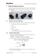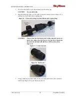
IDP 600 Terminal Series - Hardware Guide
© SkyWave Proprietary 33 T200, Version 02
If the wires are not long enough, splice similar gauge wire to the main power input
and ground wires so that they reach the fuse panel. Cover any splices with adhesive
lined heat shrink.
3.
Connect the ground wire to the grounding point selected in Section 4.3.
4.
Connect the main power input wire to the un-switched vehicle power source within
the fuse panel.
5.
Loop and secure any excess cabling.
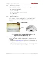
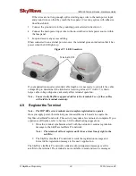
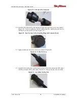
When connected to an external power source, the terminal gives an indication that it has
power when the LED lights up.
Figure 29 LED Location
If your application requires extended cable lengths, it is necessary to calculate the cable
voltage drop to determine if the terminal is receiving at least 9 V (with 1.7 A draw).
Large cable voltage drops may adversely affect terminal operation.
Note:
Connect only SkyWave approved cables to the terminal. Use of other cables
will void the terminal warranty.
4.9
Register the Terminal
Note:
The IDP 600 series terminals must complete registration to operate.
Once you apply power, the terminal goes into satellite search mode to acquire the
SkyWave IsatData Pro network. This activity may take a few minutes to complete. If you
experience difficulties, refer to Section 6 for troubleshooting suggestions.
1.
Once the terminal synchronizes itself with the network, it sends a registration
message to the SkyWave IsatData Pro network.
Note:
The terminal will not register until it has a clear line of sight to the
satellite.
2.
The SkyWave IsatData Pro network records the registration message and
forwards the registration message to the user’s application.
The SkyWave IsatData Pro network sends an acknowledgement message over the
satellite to the terminal. The terminal is now available to send and receive messages.
Terminal LED
Summary of Contents for IDP-680
Page 64: ...www SkyWave com ...


