


IDP 600 Terminal Series - Hardware Guide
T200, Version 02 32 © SkyWave Proprietary
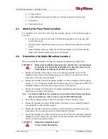
terminal connector. Damage to the terminal connector interface
or cable may otherwise result leading to hardware failure.
To protect the terminal's connector interface, follow the guidelines below:
Apply tape around the cable ends to help in routing the cable.
Secure the cable such that it does not pull on the connector or strain the terminal
connector.
Tie the cable down so that the weight of a vibrating cable will not stress or strain
the connection.
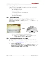
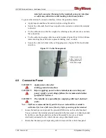
Tie the cable down using cable ties and tie holders (Figure 28) at 300 to 600 mm
intervals along the cable route to prevent chafing, wear, or strain.
Secure the cable tie holder with a self-tapping screw (Figure 28) for best holder
retention.
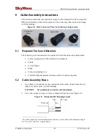
Figure 28 Cable Management
4.8
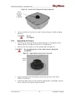
Connect to Power
CAUTION
Apply power only after
making ground connection.
CAUTION
Before applying power to the terminal, make sure that your
power supply’s rated voltage follows the recommended values
specified in Section 2.
CAUTION
The installer is responsible for complying with local electrical
codes.
Note:
SkyWave recommends that if possible the user wait until the terminal is
unblocked (i.e., has a full view of the sky) before powering up the terminal.
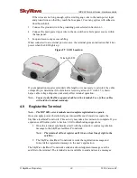
1.
Locate the main power input and the ground (GND) wires on the cable breakout.
You can connect the terminal ground to ground in the fuse panel or to chassis ground.
To do this, secure the ground wire on the cable assembly to a piece of metal
electrically connected to the vehicle chassis using a sheet metal screw.
2.
Ensure that the main power input and ground wires reach the vehicle fuse panel.
Adhesive cable tie
holder. Apply a self-
tapping screw here
for added strength.
Summary of Contents for IDP-680
Page 64: ...www SkyWave com ...


