background image


IDP 600 Terminal Series - Hardware Guide 

© SkyWave Proprietary                                                    3                                                   T200, Version 02 

Table 1 

IDP 600 Series Models 

Model 

Elevation Angle 

Connector 

GPS  

(optional) 

IDP-680 

20° - 90° 

10-pin  

side or bottom 

Yes 

IDP-690 

-15° - 90° 

10-pin  

side or bottom 

Yes 

Part numbers are specified in Table 9. 

All terminals are available in two configurations: bottom connector or side connector (see 
figures below).  

Figure 3 

IDP-680 with Side Connector 


Figure 4 

IDP-680 with Bottom Connector 


Summary of Contents for IDP-680

Page 1: ... 600 Terminal Series Hardware Guide T200 Version 02 The electronic version of this document allows you to use the built in Hyperlinks and bookmarks when using Adobe Reader SkyWave Mobile Communications Inc ...

Page 2: ...s or performance of the software Under no circumstance shall SkyWave be held liable for any direct indirect consequential or incidental damages arising from the use or inability to use the software or documentation All trademarks or registered trademarks are the property of their respective owners INMARSAT the Inmarsat logo and IsatData Pro are trademarks of Inmarsat used under license by SkyWave ...

Page 3: ... Overview of the Messaging System 1 1 2 Terminals 2 1 3 Terminal Key Features and Benefits 4 1 4 Pass Through Mode 5 1 5 Operating Modes 5 2 Compliance 7 3 Specifications 9 3 1 Connector 9 3 1 1 Connector Pin out 9 3 2 Power 10 3 2 1 Input Range 10 3 2 2 Power Consumption 11 3 2 2 1 Average Power Consumption 11 3 2 3 Load Dump Circuitry 11 3 2 4 Fuse 12 3 3 Input Output 12 3 3 1 Digital Input 13 3...

Page 4: ...ation 26 4 5 Route the Main Cable 27 4 6 Mount the Terminal 28 4 6 1 Drill Mounting Holes optional 29 4 6 2 Mount the Terminal 29 4 6 3 Apply Dielectric Grease 30 4 7 Protect the Cables and Cable Connectors 31 4 8 Connect to Power 32 4 9 Register the Terminal 33 4 10 Cleaning Instructions 34 4 11 Application Programming Interface 34 5 Cable Assembly Instructions 35 5 1 Required Tools and Materials...

Page 5: ...90 Side View Enclosure Dimensions mm 20 Figure 20 Mobile ID Location 24 Figure 21 Sample Activation Report 25 Figure 22 Sample Cable Placement in a Vehicle Cab 28 Figure 23 Bottom Connector and Side Connector IDP 680 shown 29 Figure 24 Location for Waterproof Sealing Compound 30 Figure 25 Apply Silicone Lubricant to Connector 30 Figure 26 Key Slot 31 Figure 27 Cable Connector and Locking Collar 31...

Page 6: ...s 48 List of Tables Table 1 IDP 600 Series Models 3 Table 2 Terminal Connector 9 Table 3 Terminal Electrical Pin Assignment 9 Table 4 Power Consumption Values 11 Table 5 Power Consumption Scenarios 11 Table 6 Pass Through Mode I O States 16 Table 7 Pass Through Mode Timing Specifications 16 Table 8 Pass Through Mode Power Consumption 16 Table 9 Order Part Numbers 41 Table 10 IDP 600 Series Mating ...

Page 7: ...ware components and hardware labels in this document may not be exactly as shown and are subject to change without notice CAUTION This safety symbol warns users of possible hazards to personnel to equipment or to both It includes hazards that will or can cause severe personal injury death or substantial property damage if the hazard is not avoided and hazards that will or can cause minor personal ...

Page 8: ...n Warning SkyWave recommends that this product be installed by the authorized distributor from whom it has been purchased By carrying out the installation of the product the installer assumes exclusive responsibility for and agrees to indemnify SkyWave from any injury or damage of any kind arising from the installation Limited Liability SkyWave s liability is limited to the cost of repair or repla...

Page 9: ...ny damages caused or associated with the product s misuse The end user s only remedy or recourse is against the Solution Provider and any experience with defective products should be communicated to your Solution Provider Shipping of defective product back to the Solution Provider will be in accordance with the Solution Provider s instructions and should be accompanied with a fault report SkyWave ...

Page 10: ...IDP 600 Terminal Series Hardware Guide T200 Version 02 x SkyWave Proprietary THIS PAGE INTENTIONALLY LEFT BLANK ...

Page 11: ...ta messaging terminal with built in I O data collection and processing capabilities Feature rich software tools make programming easy and shorten the design and testing time 1 1 Overview of the Messaging System SkyWave s IsatData Pro satellite messaging system is designed to support the management of mobile or fixed assets located around the world An asset fitted with one of SkyWave s satellite ba...

Page 12: ...s1 The IDP 600 series Table 1 of SkyWave mobile satellite terminals operate on the IsatData Pro network The terminals are self contained environmentally sealed compact and provide low power consumption Terminals include an omni directional antenna satellite modem GPS programmable microcontroller and several I O input output feeds capable of monitoring and controlling external sensors and devices T...

Page 13: ...Angle Connector GPS optional IDP 680 20 90 10 pin side or bottom Yes IDP 690 15 90 10 pin side or bottom Yes Part numbers are specified in Table 9 All terminals are available in two configurations bottom connector or side connector see figures below Figure 3 IDP 680 with Side Connector Figure 4 IDP 680 with Bottom Connector ...

Page 14: ...y on the terminal for emergency SOS calls The IDP 600 series terminals have the following key features and benefits Designed to be used as a standalone or incorporated into an SP solution Built in GPS receiver to calculate position speed and heading Quick and easy installation reduces labor time and costs Ships with installed firmware Flexible custom scripting Broad operational temperature range R...

Page 15: ...on processor portion of the terminal has its own independent set of modes Transmit Mode In transmit mode the terminal is transmitting a signal to the gateway Several transmissions can occur within any 5 second frame Receive Mode In receive mode the terminal is receiving a signal from the gateway This is mutually exclusive with transmit mode Sleep Mode In sleep mode the terminal draws minimal curre...

Page 16: ...P 600 Terminal Series Hardware Guide T200 Version 02 6 SkyWave Proprietary Processing Mode In its processing mode the applications processor is actively running while transmit and receive are powered down ...

Page 17: ...tions and Systems SES Harmonized EN for Low data rate Land Mobile satellite Earth Stations LMES and Maritime Mobile satellite Earth Stations MMES not intended for distress and safety communications operating in the 1 5 1 6 GHz frequency bands covering essential requirements under article 3 2 of the R TTE Directive EN 301 489 20 V1 2 1 2002 11 Electromagnetic compatibility and Radio spectrum Matter...

Page 18: ...IDP 600 Terminal Series Hardware Guide T200 Version 02 8 SkyWave Proprietary THIS PAGE INTENTIONALLY LEFT BLANK ...

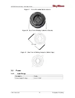
Page 19: ...ector Parameter Part Number Mating Connector Kit SA901020 001 3 1 1 Connector Pin out Figure 8 Terminal Connector Pin Assignment Male Table 3 Terminal Electrical Pin Assignment Pin Functionality Pin Functionality 1 RS 485 J17083 A 2 RS 485 J1708 B 3 GND 4 VIN 5 I O 02 6 I O 03 7 I O 01 8 I O 04 9 RS 232 Tx Output 10 RS 232 Rx Input 3 J1708 is configurable in software control ...

Page 20: ... 02 10 SkyWave Proprietary Figure 9 View of Terminal Male Connector Figure 10 Face View of Mating Connector Female Figure 11 Rear View of Mating Connector Solder Cups 3 2 Power 3 2 1 Input Range Parameter Value Power Supply Voltage 9 to 32 V DC 29 3 mm ...

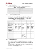
Page 21: ...2 Mobile 3 Wake to Receive Period 30 min 3 min 60 min 30 min 10 min Tx Day and Message Size Tx 48X 98 bytes 96X 98 bytes 1X 98 bytes 2X 98 bytes 2X 98 bytes GPS Fix Day 1 network 1 network 24 4 network 4 network Power Mode Fixed battery Fixed battery Mobile powered Mobile battery Mobile battery Average Power Consumption mAh day at 12 V 24 111 16 11 25 Serial terminal only On Rx Wake Up On Rx Wake ...

Page 22: ...vides protection in the event of an internal short on the terminal The internal fuse cannot be reset and is not field repairable 3 3 Input Output The terminal s four configurable I O lines are each independently operable in one of following modes Digital Input Digital Output Analog Input Disabled When disabled the I O is physically configured as an analog input ...

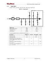
Page 23: ...own Open Closed With pull up Closed Open The input specifications are provided in the table below Parameter Minimum Typical Maximum Units Input low range 10 1 05 V Input high range 1 95 150 V Input current with weak pull down weak 1 MΩ pull down still in place Vin 3 0 V 3 µA Input source current with pull up Vin 0 0 V 75 µA Input sink current with pull down Vin 3 to 150 V 80 µA INPUT DIGITAL 1k 3V...

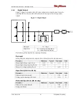
Page 24: ...ions Push pull In the push pull configuration the output is driven directly from the microprocessor Parameter Minimum Typical Maximum Units Output high voltage open circuit 2 85 3 0 3 15 V Output high voltage sourcing 25 µA 2 80 V Output low voltage sinking 25 µA 0 05 V Open Drain I O 01 to I O 03 Parameter Minimum Typical Maximum Units Sink current do not exceed 250 mA Voltage active drawing at 2...

Page 25: ...he terminal software has a sample rate 1 Hz 3 3 5 Output Bandwidth When used as a digital output either a push pull or open drain the I O circuitry s bandwidth exceeds 100 Hz Note This does not imply that the terminal software has the capability of generating high rate pulse trains at frequencies 10 Hz 3 3 6 Pass Through Mode A terminal can be configured for pass through mode when there is no appl...

Page 26: ...f no valid RS 232 level on receiver When in pass through mode the application controller samples inputs and drives the equivalent output appropriately Pass through mode time specifications are given in Table 7 Table 7 Pass Through Mode Timing Specifications Parameter Specification Baud Rate As per modem configuration Maximum Jitter on Signals Modem to External 10 µs Maximum Jitter on Signals Exter...

Page 27: ... J1708 The terminal can be configured for an RS 485 or J1708 interface It can be used for general bus or for SCADA interfacing The RS 485 J1708 does not incorporate a termination resistor The electrical characteristics of the interface are Parameter Minimum Typical Maximum Units Input Common Mode Voltage 7 0 12 V Differential Input Threshold 200 125 50 mV Output Common Mode Voltage 1 5 3 0 V Diffe...

Page 28: ...egrees elevation 3 6 GPS Standard GPS Parameter Value Receive Type GPS C A Code Frequency L1 1575 42 MHz Mean Time to First Fix Cold Start 36 s Warm Start 8 s Sensitivity Tracking 146 dBm Acquisition 136 dBm Accuracy Horizontal Position CEP 4 m Horizontal Speed CEP 0 02 m s Heading at 100 km hr speed 50 0 1 3 7 Physical Details The terminal s mechanical enclosure is a rugged impact and chemical re...

Page 29: ...s Hardware Guide SkyWave Proprietary 19 T200 Version 02 Figure 16 IDP 680 Top View Enclosure Dimensions mm Figure 17 IDP 680 Side View Enclosure Dimensions mm Figure 18 IDP 680 and IDP 690 Bottom View Enclosure Dimensions mm ...

Page 30: ... LED to indicate that the terminal has successfully powered up Section 4 8 The visual indicator LED does not indicate satellite status Its only purpose is to confirm terminal start up Parameter Value Color Red 3 9 Non Volatile Storage The IDP 600 series has non volatile flash memory that is shared by the terminal firmware and user services Parameter Value Non volatile On board Flash Storage 4 MB W...

Page 31: ...fter a non operating 12 2 km altitude test as detailed in SAE J1455 section 4 9 3 except with an ambient temperature of 40 C Thermal Shock The terminal meets all of its specifications after a thermal shock test as detailed in SAE J1455 section 4 1 3 2 Salt Spray Atmosphere The IDP 680 meets all of its specifications after a salt spray test as detailed in SAE J1455 section 4 3 3 1 Immersion The ter...

Page 32: ...fications after a fungus test as detailed in SAE J1455 section 4 6 3 Dust and Sand Bombardment The terminal meets all of its specifications after a dust and sand bombardment test as detailed in SAE J1455 section 4 7 3 The terminal meets the acceptance conditions of IEC 60529 section 13 6 2 after a dust and sand bombardment test as detailed in IEC 60529 section 13 4 Drop Test The terminal meets all...

Page 33: ...including legal fees The installer also agrees to hold harmless SkyWave including its agents employees and assigns from any wrongful or negligent act or omission committed by any subcontractor or other person employed by or under the supervision of the installer for any purpose and to indemnify SkyWave including its agents employees and assigns from every expense liability or payment arising out o...

Page 34: ...KYXXXX The mobile ID is located on the bottom of the terminal and on the shipping box Figure 20 Mobile ID Location 1 Record the mobile ID in APPENDIX E for future reference Note SkyWave may activate terminals on the network prior to or after shipping based on the Purchaser SP agreement 4 2 3 Contact SkyWave to Activate the Terminal In order to send or receive any message you must activate the term...

Page 35: ...rs Waterproof sealing tape Waterproof sealing compound such as RTV silicone bottom connector version only Qty 1 Custom cable6 SkyWave recommends that the Solution Provider supply the end user with a custom built cable 4 2 5 Required Tools You require the following tools to install a terminal Drill 6 Refer to Section 5 for instructions on making a custom cable The Mobile ID is the serial number whi...

Page 36: ...le installation this means at the highest point on the vehicle or vessel where it has a clear view of the sky in all directions Mount the terminal so that the Inmarsat satellite is within α degrees of the mounting surface α 0 to 90 degrees for IDP 680 terminals and 15 to 90 degrees for IDP 690 terminals Make sure that the line of sight is clear of obstructions Mount the terminal on a flat surface ...

Page 37: ...ware e g emergency lights that could interfere with satellite communications Mount the terminal on the driver s side of the vehicle if possible when there is a possibility of strikes by overhanging tree branches Do not install the terminal inside the truck under the roof liner Once you have picked the mounting location mount the terminal refer to Section 4 5 4 5 Route the Main Cable Consider the f...

Page 38: ...This will help to minimize the amount of cable routed along the floor of the cab Where possible route the cable through existing holes in the floor or the firewall of the engine compartment 3 Route the cable starting from the terminal to the fuse panel or battery source Note SkyWave recommends that you tape cable ends to prevent dirt from collecting on the contacts 4 6 Mount the Terminal CAUTION P...

Page 39: ...unting holes and the connector hole The direction of the terminal with a bottom connector is not important 2 Drill the four mounting holes using the drill with the 5 5 mm bit 3 Punch or drill the 30 mm hole for the connector bottom connector only 4 Continue with the steps below for Mount the Terminal 4 6 2 Mount the Terminal 1 Apply waterproof sealing compound such as RTV silicone to the locations...

Page 40: ...ilicone lubricant grease will make sure that there is a watertight seal 2 Insert the tube into the male end of the mating connector Figure 25 CAUTION Do not apply pressure to the cable connector during the installation Figure 25 Apply Silicone Lubricant to Connector 3 Squeeze the lubricant into the mating connecter opening until it is full Some lubricant will spill out 4 Connect the cable connecto...

Page 41: ...is properly engaged Figure 27 Cable Connector and Locking Collar 6 Wipe off any extra lubricant around the connector 7 Wrap the mating connector with waterproof sealing tape if using the connector in changing weather conditions 4 7 Protect the Cables and Cable Connectors CAUTION Cable management and connector strain relief must be incorporated in the installation SkyWave highly recommends securing...

Page 42: ...tention Figure 28 Cable Management 4 8 Connect to Power CAUTION Apply power only after making ground connection CAUTION Before applying power to the terminal make sure that your power supply s rated voltage follows the recommended values specified in Section 2 CAUTION The installer is responsible for complying with local electrical codes Note SkyWave recommends that if possible the user wait until...

Page 43: ...ps may adversely affect terminal operation Note Connect only SkyWave approved cables to the terminal Use of other cables will void the terminal warranty 4 9 Register the Terminal Note The IDP 600 series terminals must complete registration to operate Once you apply power the terminal goes into satellite search mode to acquire the SkyWave IsatData Pro network This activity may take a few minutes to...

Page 44: ...ardware Guide T200 Version 02 34 SkyWave Proprietary 4 10 Cleaning Instructions Wash the terminals with mild soaps or detergents 4 11 Application Programming Interface Refer to T202 for programming information for the terminals ...

Page 45: ...od A cable7 appropriate for the terminal s environment A knife A wire stripper Solder A fine tip soldering iron A flexible high temperature silicone sealant for outdoor exposure 5 2 Cable Assembly Steps 1 Use a knife to cut and remove the outer jacket of the cable 20 mm from the end Figure 31 and remove any foil shielding CAUTION Be careful not to nick the wire insulation 2 Use a wire stripper to ...

Page 46: ...a coupling ring Figure 32 Cable with Sealing Nut Back Shell and Coupling Ring CAUTION Ensure that the black back shell cable grommet is present inside the cable grip area Figure 33 and the red gasket is present and oriented with flat face visible as shown in Figure 34 Figure 33 Cable Grommet Figure 34 Red Gasket 5 Using a soldering iron and solder tin the wires and solder them to the connector sol...

Page 47: ...36 O Ring over Connector Body 7 Slide the coupling ring over the connector body and give it a twist to prevent it from falling off 8 Use silicone sealant to completely fill the end of the connector and the area between the wires Figure 37 Figure 37 Silicone in the Connector 9 Slide the back shell up the cable as close as possible to the connector body and fill it with silicone sealant Figure 38 ...

Page 48: ...hell align the coupling ring key feature with the slot in the connector body Figure 39 Figure 39 Key Features in the Coupling Ring and Connector Body 11 Apply sealant over the cable exit area as shown in Figure 40 Figure 40 Cable Exit Area 12 Assemble the sealing nut over the back shell until the cable grip makes full contact with the perimeter of the cable jacket Figure 41 Wipe away any excess se...

Page 49: ...k and registration normally takes a few minutes If the terminal fails to register or report Ensure that the antenna has a clear line of sight to the satellite The terminal must operate outdoors and be unobstructed by buildings forest canopy and rock cuts Check that no objects or debris are on the antenna i e atop the terminal and blocking transmission Verify with your SP that the terminal is assig...

Page 50: ...IDP 600 Terminal Series Hardware Guide T200 Version 02 40 SkyWave Proprietary THIS PAGE INTENTIONALLY LEFT BLANK ...

Page 51: ...r Part Numbers Terminal Part Number Side Connector Bottom Connector IDP 680 with standard GPS SM201016 SXG SM201016 BXG IDP 690 with standard GPS SM201009 SXG SM201009 BXG Kits Cable Connector and Solder Cup Kit SA901020 001 Pole Mount Kit SA900503 Contact your Account Executive for additional products and ordering codes ...

Page 52: ...kyWave Proprietary APPENDIX B Activation Information Server User Name ________________________________________________________ Password _______________________________________________________________ Terminal Type Description Mobile ID NNNNNNNNSKYXXXX Location ...

Page 53: ...ts There are a total of ten pins on this blunt cut cable two connect the terminal to an RS 232 console serial port or an RS 485 four wires to connect to external I O lines and one each for ground and voltage The cable has an over molded connector Figure 42 IDP 600 Series Mating Cable Specifications Parameter Value Length Maximum length 25 meters Temperature 40 C to 85 C Ultraviolet rating UV stabi...

Page 54: ...tor Face View Table 10 IDP 600 Series Mating Cable Color Code Position Color Wire Gauge Functionality 1 White 22 AWG RS 485_A 2 Grey 22 AWG RS 485_B 3 Black 20 AWG Ground 4 Red 20 AWG VIN Vbatt 5 Green 22 AWG I O 02 6 Blue 22 AWG I O 03 7 Brown 22 AWG I O 01 8 Purple 22 AWG I O 04 9 Orange 22 AWG RS 232 Tx output 10 Yellow 22 AWG RS 232 Rx input ...

Page 55: ... 600 series terminal to be installed in place of a DMR 800 The cable has eight connectors and the RS 485 connections on the IDP 600 series terminal are left unconnected Figure 44 IDP 600 Series to DMR 800 Adapter Cable Specifications Parameter Value Length 610 mm 51 mm Temperature 40 C to 85 C Material PVC jacket 30 mils thick black Ultraviolet rating UV stabilized ...

Page 56: ...y Figure 45 IDP Connector End Pin Out Figure 46 DMR 800 Mating Connector End Pin Out Table 11 Cable Connector Pin Out IDP Position DMR 800D Position Wire Gauge 1 N C 2 N C 3 4 18 AWG 4 5 18 AWG 5 6 20AWG 6 7 20 AWG 7 1 20 AWG 8 8 20 AWG 9 2 20 AWG 10 3 20 AWG Key Slot Key Slot ...

Page 57: ...m Temperature 40 C to 85 C Material PVC jacket 30 mils thick black Ultraviolet rating UV stabilized cable jacket Rating IP67 when mated Minimum bend radius 25 mm CAUTION Cable management and connector strain relief must be incorporated in the installation SkyWave highly recommends securing the cable at regular intervals along its length as part of the installation to prevent cable wear and elimina...

Page 58: ... RS 485_A 2 2 22 AWG RS 485_B 3 3 20 AWG Ground 4 4 20 AWG VIN Vbatt 5 5 22 AWG I O 02 6 6 22 AWG I O 03 7 7 22 AWG I O 01 8 8 22 AWG I O 04 9 9 22 AWG RS 232 Tx output 10 10 22 AWG RS 232 Rx input Figure 48 Raw Cable Details Overall Shield Aluminum Foil Overall Drain PVC Jacket Black UV Stable 2 x Power Ground 2 x RS 232 2 x RS 485 Twisted Pair I O Drain I O Shield Aluminum Foil 4 x I O ...

Page 59: ...ies Hardware Guide SkyWave Proprietary 49 T200 Version 02 Overall Shield Aluminum Foil Overall Drain PVC Jacket Black UV Stable 2 x Power Ground 2 x RS 232 2 x RS 485 Twisted Pair I O Drain I O Shield Aluminum Foil 4 x I O ...

Page 60: ...check the template against actual hardware for dimensional accuracy If it is not correct DO NOT USE THIS TEMPLATE Nominal Dimensions Shown Ø 5 5 mm 7 32 in 4 PLACES Ø 30 0 mm 1 3 16 in Bottom Connector Mount ONLY Place RTV Silicone in this region 360 prior to mounting 101 6 mm 4 0 in 101 6 mm 4 0 in 50 8 mm 2 0 in 50 8 mm 2 0 in ...

Page 61: ...2 Documentation Version Version Date Details 02 Nov 2011 See What s New section for details 01 Aug 2011 Official customer release 18 Jul 2011 Limited customer release 17 Jun 2011 Limited customer release 13 Apr 2011 Limited customer release 10 Feb 2011 Limited customer release ...

Page 62: ...eral Communications Commission GND ground GPS Global Positioning System I O input output IEC International Electrotechnical Commission kgf cm kilogram force centimeter LED light emitting diode RF radio frequency RoHS Restriction of Hazardous Substances R TTE Radio and Telecommunications Terminal Equipment Rx receive SP Solution Provider Tx transmit ...

Page 63: ...20 figure 4 mass 20 Industry Canada 7 IsatData Pro network description 1 features 1 maximum messages from mobile 1 maximum messages to mobile 1 J1708 17 key slot 31 LED 20 33 locking collar 31 mobile ID format 24 location 24 NVM storage 20 operating modes applications processing 6 receive 5 sleep 5 transmit 5 part numbers 9 16 41 R TTE Directive 7 registration 33 RoHS 7 RS 232 17 RS 485 17 safety ...

Page 64: ...www SkyWave com ...

Reviews: