background image

49

SKOPE BackBar X

Replacement Procedures

Service Manual

Recommended

Service

Procedures

SKOPE recommend the SKOPE Cyclone® demountability and exchangea-
bility philosophy, which in essence means:

The customer must not be inconvenienced during system maintenance.

In the unlikely event of Refrigeration failure, an exchange unit is simply 
swapped in a matter of minutes. There is no cabinet down time or unloading 
product. In one short visit, the customer's inconvenience ends. The faulty 
Cyclone® is then removed to the workshop for repair as time allows.

For a suspected refrigerant problem

Disconnect the evaporator fan motor and with the system running, a ‘frost 
line’ will become obvious (after approximately 5 minutes): Entire evaporator, 
accumulator, and suction line right up to compressor must be frosting. 
Compressor at suction inlet will sweat.
If these conditions are not met, the system is faulty, either short of refriger-
ant, compressor not pumping efficiently, or capillary restriction. The system 
must then be opened (see Refrigerant R134a Handling Precautions section) 
and gauges temporarily fitted (i.e. either temporarily fit line piercing valves, 
or braze in service lines).

Short of refrigerant

Where the frosting effect is shorter than required (unless all refrigerant is 
lost, where there is no frosting effect). Only a small amount of refrigerant will 
exit the system. A leak test (refrigerant / dry nitrogen mix, up to 250 psig) 
should be performed to locate the leak. If no leak is found, a pressure test 
should be performed (dry nitrogen only, up to 250 psig) if there is no pres-
sure drop over 24 hours, the fault should be treated as a capillary restriction.

Compressor not pumping efficiently

Where the frosting effect is not as cold as it should be. Symptoms include: 
compressor body hotter than normal, condenser cooler than normal, and the 
compressor may make an unusual hissing sound. All of these symptoms 
depend on the severity of the problem.
The only way to prove a pumping problem is to perform a compressor pump-
down test: braze closed compressor suction line, open discharge line; then 
run the compressor to pull a vacuum on a vacuum gauge.
The compressor should pull down to approximately 30" Hg (inches of mercu-
ry) or 101 kPa vacuum, then turn the compressor off and this vacuum must 
be held without any loss for 5 minutes. If the Compressor does not pass 
these tests; it is not pumping efficiently and must be replaced.
There are different methods to proving pumping efficiency. If the test is 
performed with a system charged with refrigerant, a deep vacuum will not be 
achieved.

Capillary restriction

With a totally blocked capillary, there will be no refrigeration effect. A partially 
blocked capillary may have similar symptoms to a system being short of 
refrigerant. Flush a restricted capillary with dry nitrogen. If the capillary will 
not clear, it must be replaced.
After the repair, the drier must be replaced. The Cyclone® must be fully 
evacuated and charged to the volume of refrigerant indicated on the 
Cyclone® serial/rating label. All service lines must be purged.
Finally, pinch-off the gauge process lines (or remove line piercing valves) 
and braze the system closed. SKOPE recommend against leaving service 
valves in the system as these are prone to leak (and are open to abuse). 
Perform a final system leak test.

Summary of Contents for B2412

Page 1: ...BackBar X SKOPE Horizontal Chiller Service Manual MAN11155 Rev 1 4 Jun 2020 BB380X 2SW...

Page 2: ...k Infringement The SKOPE trademark on this product is infringed if the owner for the time being does any of the following Applies the trade mark to the product after their state condition get up or pa...

Page 3: ...Settings 15 Temperature Probe Readings 15 Wiring Termination 15 Programming the Electronic Controller 16 Temperature Setpoint 16 Parameters 16 Parameter History 17 3 Wiring Model BackBar X Integral S...

Page 4: ...Removal 43 Integral Refrigeration Unit 44 Refrigeration Unit Assembly 44 Unit Front Cover 44 Unit Electrics Box 45 Refrigeration Unit Removal 46 Evaporator Fan Assembly 47 Condenser Fan Assembly 48 Co...

Page 5: ...al chiller 2 BB580X 3SW B2413 Integral chiller 3 BB780X 4SW B2414 Integral chiller 4 BB380Xr 2SW RB2412 Remote chiller 2 BB580Xr 3SW RB2413 Remote chiller 3 BB780Xr 4SW RB2414 Remote chiller 4 BB380XT...

Page 6: ...Self closing double glazed toughened single Low E argon filled safety glass doors Optional door locks Door number 2 3 4 Operating conditions Maximum operating temp 40 C 40 C 40 C Product temp range pr...

Page 7: ...le glazed toughened single Low E argon filled safety glass doors Optional door locks Door number 2 3 4 Operating conditions Maximum operating temp 40 C 40 C 40 C Product temp range product mass averag...

Page 8: ...lf closing double glazed toughened single Low E argon filled heated safety glass doors Optional door locks Door number 2 3 4 Operating conditions Maximum operating temp 40 C 40 C 40 C Product temp ran...

Page 9: ...glazed toughened single Low E argon filled heated safety glass doors Optional door locks Door number 2 3 4 Operating conditions Maximum operating temp 40 C 40 C 40 C Product temp range product mass av...

Page 10: ...is housed inside the electronic controller box assembly in front of the refrigeration unit The electronic controller controls and displays the chiller temperature and signals temperature alarms To ens...

Page 11: ...et to sense temperature 2 Up Button Used for programming 3 Set mute Press to mute the alarm Press and hold to access parameters Also used for programming 4 Light down Press to switch the cabinet light...

Page 12: ...nd condenser fan To verify check that the FAN light is lit on the electronic controller faceplate Temperature Probes Three temperature probes feed data to the electronic controller the control probe t...

Page 13: ...ture inside the chiller is too cold and an alarm sounds The controller will automatically reset the alarm once the temperature inside the chiller raises High temperature alarm An alarm sounds The temp...

Page 14: ...old This happens if the control probe at the evaporator air out detects the interior temperature below 1 C parameter St CCt for more than 30 minutes parameter CCd The lights will stay on and cannot be...

Page 15: ...oller faceplate during normal operation 1 If parameter 4 is not set to 1 it can be changed to 1 to view the control probe temperature reading Condenser probe To view the condenser probe temperature re...

Page 16: ...w the steps below to access the locked parameters To access the locked parameters 1 Press and hold the Set mute button for 3 seconds until PS is shown on the display indicating entry into the controll...

Page 17: ...ease the value of the parameter 8 Press the Set mute button to temporarily save the new value The display shows the parameter code IMPORTANT If no buttons are pressed for 60 seconds or the power is di...

Page 18: ...e Protection Parameters CCt 2 0 C C 0 1 20 0 Cold Climate Protection Temperature Delta CCd 30 mins C 0 199 Cold Climate Protection Delay Pull Down Mode Parameters Pt 127 C C 0 127 Pull down Mode Activ...

Page 19: ...abled A11 2 C 0 5 2nd Input Configuration A12 3 C 0 16 Number of cA alarm events to trigger manual reset CA alarm A13 24 hrs C 0 240 cA alarm counter reset delay A14 60 mins C 0 240 cA alarm reset del...

Page 20: ...Protection Parameters CCt 2 0 C C 0 1 20 0 Cold Climate Protection Temperature Delta CCd 30 mins C 0 199 Cold Climate Protection Delay Pull Down Mode Parameters Pt 127 C C 0 127 Pull down Mode Activat...

Page 21: ...led A11 0 C 0 5 2nd Input Configuration A12 3 C 0 16 Number of cA alarm events to trigger manual reset CA alarm A13 24 hrs C 0 240 cA alarm counter reset delay A14 60 mins C 0 240 cA alarm reset delay...

Page 22: ...T4 N BU Pillar Element Pillar Element Door FrameElement Perimeter Element T5 1 BU WH RD S8 4 P8 4 WH BN WH S6 4 P6 4 BK BK BN Note Items in shaded box are for multiple doors BU BU BU BN WH WH BK BU L...

Page 23: ...obe Evaporator Probe BN BU BK WH BK BK T5 1 BN Note Items in shaded box are For multiple doors BN BU BU BU WH BU M BK BK Condensate Fan P6 1 S6 1 P6 2 S6 2 LEGEND S1 P1 IEC cabinet socket plug S9 P9 C...

Page 24: ...24 Spare Parts Service Manual SKOPE BackBar X 4 Spare Parts Cabinet Assembly BB X Integral Series 1 2 3 4 4 10 5 6 7 8 9 11 12 13 14 15 16 17 18 19 20 21 22 BB780X 4SW left hand cabinet unit pictured...

Page 25: ...be cover diffuser B2002 E71 B2003 E71 B2003 E71 16 Refrigeration unit cover including louvre RH B2412 130R B2412 130R B2412 130R Refrigeration unit cover including louvre LH B2412 130L B2412 130L B241...

Page 26: ...26 Spare Parts Service Manual SKOPE BackBar X Cabinet Assembly BB X Remote Series 1 16 17 2 3 4 4 7 8 13 14 15 5 6 10 9 11 12 18 19 20 BB780Xr 4SW left hand cabinet unit pictured...

Page 27: ...2 Bottom hinge LH B2412 394 B2412 394 B2412 394 13 LED light tube ELL10742 ELL10743 ELL10743 14 Light tube holder ELZ6270 ELZ6270 ELZ6270 15 Light tube cover diffuser B2002 E71 B2003 E71 B2003 E71 16...

Page 28: ...tropical GLD11432R Door assembly LH standard GLD11431L Door assembly LH tropical GLD11432L 1 Gasket GKT11546 2 Bush spacer PLM11298 3 Bush PLM5075 4 Plug 16mm PLM11448 5 Plug 14mm door with no door lo...

Page 29: ...LH including mains flexible power cord B2412 E80L 1 IEC socket outlet ELK8880 2 2 Pole rocker switch ELS0495 3 EMI filter ELZ10136 Mains flexible power cord not pictured C9011 E53 No Description SKOP...

Page 30: ...ontroller ELZ11478 100 2 Electronic controller housing lid HB0070206126 3 Electronic controller housing base HB0070206125 4 Cable clamp HB0070206127 No Description SKOPE Part No 0 Electronic controlle...

Page 31: ...ctrics box assembly LH unit UE40ABF R86L 1 Fuse 5A ELZ9640 Fuse holder ELZ9655 2 Unit electrics box lid UE40ABF R88 Unit IEC supply flexible cord not pictured UE40ABF E53 Condenser temperature probe i...

Page 32: ...32 Spare Parts Service Manual SKOPE BackBar X Refrigeration Unit Assembly BB X Integral 2 1 3 4 5 6 7 8 9 10 12 11 13 14 UE30ABF LH unit pictured...

Page 33: ...mpressor CPR6108 CPR7344P Compressor relay ELR2729NC ELR2729NC Start capacitor ELC2369NC ELC2369NC 4 Evaporator coil CLS9902R CLS9902R 5 Condenser coil CLS9317 CLS9317 6 Condensate tray UE11AA 992 UE1...

Page 34: ...R 103ID used in BB380Xr 580Xr and BB380XTr UE40ABR 103ID used in BB780Xr and BB580XTr 780XTr 1 Evaporator box foamed UE40ABF 970 UE40ABF 970 2 Evaporator lid foamed B2002 980 B2002 980 3 Evaporator co...

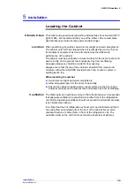
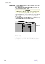
Page 35: ...of the cabinet is shielded from impact and moisture with either a SKOPE provided bench top or with a custom or existing bench top When installing the cabinet Avoid direct sunlight and warm draughts et...

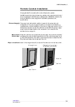
Page 36: ...isolation switch is switched on see page 40 Integral cabinets The power cord can be retrieved from either the rear or side power port Any surplus cord length can be left inside the compartment Remote...

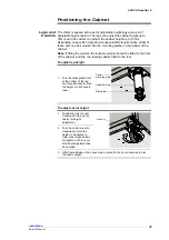
Page 37: ...tors the lockable castors should be fitted to the front of the cabinet and the non locking castors fitted to the rear To adjust leg height To adjust castor height 1 Turn the black plastic foot at the...

Page 38: ...from the shelves Clip the shelf support brackets into the shelf support strips at the desired heights and fit the shelves The shelves may be positioned at different heights to suit various products A...

Page 39: ...stallation of the remote refrigeration system If the chiller does not power up when the cabinet is connected to the power supply check that the isolation switch in the evaporator unit compartment is s...

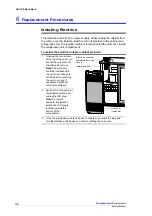
Page 40: ...ews at the top of the unit cover and lift the unit cover off the cabinet to remove Note The electronic controller is attached to the unit cover Take care of cables when removing the unit cover and if...

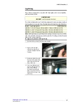
Page 41: ...direction To replace the interior LED light tube IMPORTANT DO NOT use fluorescent tubes Model Light description SKOPE Part No BB380X 1 x 20W T8 frosted LED tube 26 900mm 5500K ELL10742 BB580X 1 x 24W...

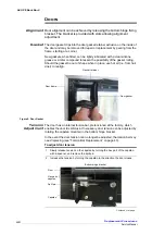
Page 42: ...ape when in place use hot air i e from hair drier to realign Tension Adjustment The door has an internal torsion bar pretensioned at the factory which enables the door to self close If necessary door...

Page 43: ...ll need manoeuvring to allow the flat hook end to clear the hinge hole Note If the torsion bar cannot be removed cut the torsion bar as far down as possible and leave the remainder in the door 4 Remov...

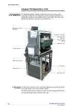
Page 44: ...d specific and cannot be reversed LH unit pictured Unit Front Cover To remove the unit front cover undo the two fixing screws at the top of the cover then lift the cover up and off the cabinet To refi...

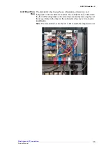
Page 45: ...rics and refrigeration unit and cabinet connectors The unit electrics box is fixed onto the front of the refrigeration unit and can be accessed by removing the unit front cover Refer to the label on t...

Page 46: ...supply plug from the electrics box 3 Detach the electronic controller from the unit cover To do this grasp with your thumb over the top and fingers wrapped around and push the back of the assembly dow...

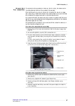
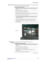
Page 47: ...unit front cover and isolate the chiller fom the power supply see page 40 2 Disconnect evaporator motor flex from unit electrics box 3 To remove the assembly via the cabinet interior when cabinet is...

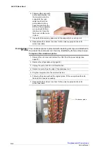
Page 48: ...operating correctly The compressor must be supplied with consistent voltage over 220 volts ensure the voltage does not drop at start up If the voltage does drop ensure the unit has a direct power supp...

Page 49: ...here is no pres sure drop over 24 hours the fault should be treated as a capillary restriction Compressor not pumping efficiently Where the frosting effect is not as cold as it should be Symptoms incl...

Page 50: ...re sensitive polyolester POE compressor oil The system especially compressor must only be open for the very minimum time to prevent moisture ingression All parts required for servicing must be at hand...

Page 51: ...he controller has various programmable parameters that effect operation such as time delay and defrost modes Any suspected failure must be double checked Confirm all wiring and terminations are correc...

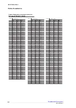
Page 52: ...11 07 77 1 87 1 82 1 77 28 103 90 100 50 97 20 23 10 90 10 78 10 66 78 1 81 1 77 1 72 27 98 68 95 52 92 45 24 10 49 10 38 10 27 79 1 76 1 72 1 67 26 93 80 90 84 87 97 25 10 10 10 00 9 90 80 1 72 1 67...

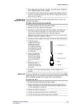
Page 53: ...raw from the evaporator box 5 Plug the new probe into the unit electrics box 6 Following the same path as the original probe run the new probe into the evaporator box use cable ties to hold the probe...

Page 54: ...mp the fins to secure the probe in place 7 Use putty to seal up any gaps around the evaporator box entry point 8 Reassemble the cabinet reconnect to the power supply and check for correct operation 1...

Page 55: ...nd the bottom grille on the unit cover Take care of the condenser coil fins when cleaning To clean the condenser coil Cabinet When necessary wipe both the interior and exterior of the cabinet with a d...

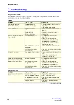
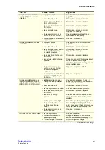
Page 56: ...is in a suitable location see page 35 Cabinet doors are opened excessively Ensure doors are closed more often Unit and or door seals compromised Check unit and door seals and service as necessary Pro...

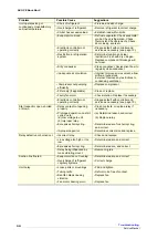
Page 57: ...sor motor has winding open or shorted Check continuity and resistance Replace compressor if faulty Internal mechanical trouble in compressor tight May be lubrication Replace compressor Compressor star...

Page 58: ...er dirty if applicable Clean or replace Faulty fan motor Check rotation Replace if necessary Electronic controller not operating correctly Diagnose fault with controller and service as necessary see p...

Page 59: ...SKOPE Contacts SKOPE Industries Limited A B N 73 374 418 306 AU 1800 121 535 NZ 0800 947 5673 skope skope com www skope com...

Reviews: