5
3.1
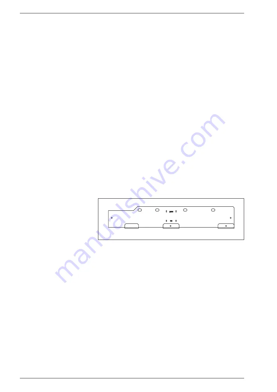
BOILER SUPPORT BRACKET
For the mounting of the support bracket of
the boiler, which is supplied, observe the fol-
lowing instructions (fig. 6):
– Fix the bracket to the wall with appropri-
ate fastenings.
– Check with a spirit level that it is perfect-
ly in horizontal plane.
3.2
CONNECTING UP SYSTEM
Before proceeding to connect up the boil-
er, you are recommended to make the air
circulating in the piping in order to elimi-
nate any foreign bodies that might be
detrimental to the operating efficiency of
the appliance.
When making the hydraulic connections,
make sure that the dimensions indicated in
fig. 1 are respected.
The discharge pipe of the safety valve
must be connected to a collector funnel
for channelling away any discharge if the
safety valve goes into action.
The gas connection must be made using
seamless steel pipe (Mannesmann type),
galvanized and with threaded joints provid-
ed with gaskets, excluding three-piece con-
nections, except for initial and end connec-
tions. Where the piping has to pass through
walls, a suitable insulating sleeve must be
provided. When sizing gas piping, from the
meter to the boiler, take into account both
the volume flow rates (consumption) in
m
3
/h and the relative density of the gas in
question. The sections of the piping making
up the system must be such as to guaran-
tee a supply of gas sufficient to cover the
maximum demand, limiting pressure loss
between the gas meter and any apparatus
being used to not greater than:
– 1.0 mbar for family II gases (natural gas);
– 2.0 mbar for family III gases (butane or
propane).
An adhesive data plate is located inside the
front panel; it contains all the technical data
identifying the boiler and the type of gas for
which the boiler is arranged.
3.2.1
Filter on the gas pipe
The gas valve is supplied ex factory with an
inlet filter, which, however, is not adequate
to entrap all the impurities in the gas or in
gas main pipes.
To prevent malfunctioning of the valve, or in
certain cases even to cut out the safety
device with which the valve is equipped,
install an adequate filter on the gas pipe.
3.3
FLUE AND TERMINAL
PREPARATION
If the wall thickness is less than 0.5 m (19
in) the flue/air duct may be fitted without
access to the outside wall providing that the
optional wall liner kit is used. (This consists
of a steel pipe, 0.5 m long and 129 mm out-
side diameter with a 1 mm wall thickness).
3.3.1
Flue/air duct lengths
– Determine whether an extension duct is
required with reference to the
Z
dimen-
sion shown in fig. 8.
Alternatively max. flue lengths informa-
tion is given in
Table 3.
Z
Dimension UP TO 945 mm.
No extension duct required.
Z
Dimension greater than 945 mm and
up to 1,760 mm.
One extension duct kit required.
Z
Dimension greater than 1,760 mm
and up to 2,575 mm. Two extension
duct kits required.
3
INSTALLATION
Fig. 6
If an extra vessel is required, ensure that
the total capacity of both vessels is ade-
quate. Further details are available in the
current issues of BS5449 and BS6798.
NOTE: If the pressure gauge indicates
2.65 bar or greater when the appliance is
at maximum temperature with all radia-
tors in circulation an extra expansion ves-
sel is required.
2.8.3
Pressure gauge
A led type pressure display is located on the
appliance facia panel.
2.8.4
Safety valve
A safety valve set at 3 bar (43.5 psi) is fit-
ted to the appliance and a discharge pipe
is routed to outside of the appliance.
This discharge pipe should be extended to
terminate safely away from the appliance
and where a discharge would not cause
damage to persons or property but would
be detected. The pipe should be able to
withstand boiling water, be a minimum of 15
mm in diameter, and not include any hori-
zontal runs prone to freezing.
2.9
D.H.W. SYSTEMS
– The authority of the local Water Company
should be obtained before the appliance
is connected to the cold water mains sup-
ply. Check that the mains supply pressure
is within the prescribed limits (point 1.3).
If necessary, a pressure reducing valve
should be fitted to the mains supply
before the D.H.W. inlet connection.
– The final 600 mm (24 in) of the mains
supply pipe to the boiler must be copper.
– If the appliance is installed in an area
where the temporary hardness of the
water supply is high, say over 150 ppm,
the fitting of an in line scale inhibitor may
be an advantage. Consult the Local Water
Undertaking if in doubt.
– Devices capable of preventing the flow of
expansion water: e.g. non return valves
and/or loose-jumpered stop cocks should
not be fitted unless separate arrange-
ments are made for expansion water.
– For specific information relating to fit-
tings (eg. Showers, washing machines
etc.) suitable for connection in the
D.H.W. circuit, consult the Local Water
Undertaking, however the following infor-
mation is given for guidance.
2.9.1
Domestic hot/cold water supply
taps and mixing taps
All equipment designed for use at mains water
pressure is suitable.
Summary of Contents for Planet Super 4 F.S.
Page 1: ...Planet Super 4 F S Installation Servicing Instructions GB...
Page 27: ......
Page 29: ...Planet Super 4 F S User Instructions GB...
Page 30: ......
Page 41: ...Planet Super 4 W M...
Page 74: ......
Page 75: ......


