SIGMAKOKI HIT-M User Manual Download Page 70


Copyright 2018, SIGMAKOKI Co.,Ltd. 


70

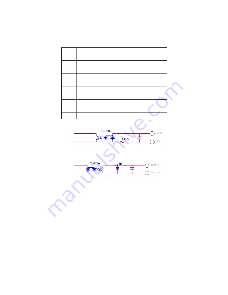
6-2.Connector Pin Assignments


6-2-1 I/O Connector 

No. 

Description 

No. 

Description 

IN COM 

11 

IN1 

IN2 

12 

IN3 

IN4 

13 

14 

OUT1 (H) 

15 

OUT1 (L) 

OUT2 (H) 

16 

OUT2 (L) 

OUT3 (H) 

17 

OUT3 (L) 

OUT4 (H) 

18 

OUT4 (L) 

19 

10 

+V (DC24V) 

20 

GND 

Connector 10220-52A2PE (by Sumitomo 3M Limited) used 


Figure 5-2-1

IN1

4 Input Circuit Diagram 


Figure 5-2-2

OUT1

4 Output Circuit Diagram 


Summary of Contents for HIT-M

Page 1: ...1 Copyright 2018 SIGMAKOKI Co Ltd User s Manual Link controller for multi axes stages HIT M HIT S HIT SH...

Page 2: ...on contained in these materials including product data diagrams charts programs and algorithm please be sure to evaluate all information and products SIGMAKOKI CO LTD assumes no responsibility for any...

Page 3: ...iving Current 13 3 3 3 3 2 2 2 2 Settings Motor Divide Settings Motor Divide Settings Motor Divide Settings Motor Divide 14 3 3 3 3 3 Memory Switch settings 3 Memory Switch settings 3 Memory Switch se...

Page 4: ...dicate warnings and cautions The exact nature of the warning or caution is indicated by the symbol inside the symbol at left indicates risk of electrocution Symbols enclosed in a circle mark indicate...

Page 5: ...by the equipment may be impaired WARNING Do not use this product in the presence of flammable gas explosives or corrosive substances in areas exposed to high levels of moisture or humidity in poorly v...

Page 6: ...rchase 1 2 Overview This controller is a Multi Axes Moterized Stage Controller built in 5 Phase stepping motor Driver Maximum 8 axes connection possible Since micro step driver is installed it is poss...

Page 7: ...O control Please interface with 10120 3000PE by 3M Limited 1 Please use a crossover cable when directly Connecting HIT M to PC And a straight cable When connecting through a HUB HIT S HIT SH LAN cabl...

Page 8: ...nector When control by RS232C Interface through PC please use RS232C 7 USB Connector When control by USB Interface trough PC please use USB 8 LINK Connector In case of connection between HIT M and HIT...

Page 9: ...ter above Please refer to 3 1 settings for motor driving current for further details 7 STOP Potentiometer The current delivered when the motor is stopped can be set by adjusting STOP potentiometer abo...

Page 10: ...traight LAN cable for connecting HIT M and HIT S and HIT SH 6 Connector for Stage Driver Connects to the cable attached to the motorized stage in use 7 Power Supply Terminal DC 24V 2A Power Supply 8 F...

Page 11: ...CS 20 35 X in No 3 procedure 2 2 Interface between HIT M and HIT S HIT SH 1 How to connect HIT M and HIT S HIT SH Here it shows the case that HIT M is connected to HIT S In the case of HIT SH it is t...

Page 12: ...please refer to 3 4 LAN Settings 2 4 Power Supply Power supply should be done as instructed below Use DC24V for everything of HIT M HIT S HIT SH First switch HIT S and HIT SH on Next switch HIT M on...

Page 13: ...et with RUN potentiometer Its factory default is set to 0 75A Phase Pot Scale 0 1 2 3 4 5 6 RUN current A Phase 0 0 17 0 35 0 66 0 75 0 9 1 1 Stopping current settings STOP current Electric current wh...

Page 14: ...No 8 9 A B C D E F Motor Divide 25 40 50 80 100 125 200 250 Setting of the Motor Divide Motor Divide can be set with STEP switch Its factory default is set to 20 Division When change Motor Divide the...

Page 15: ...1000 200 8 Speed 3 S 1 999999999 70000 9 Speed 3 F 1 999999999 700000 10 Speed 3 R 1 1000 200 11 Speed 4 S 1 999999999 100000 12 Speed 4 F 1 999999999 1000000 13 Speed 4 R 1 1000 200 14 MODE_SEL SHOT...

Page 16: ...normal condition At abnormal condition LED will be light 3 4 2 INTERFACE No Memory Switch contents Setting Range Select items Default value 1 INTERFACE RS232C USB Ethrnet RS232C 2 RS232C_FLOW ON OFF O...

Page 17: ...25 40 50 80 100 125 200 250 20 8 Divide7 1 2 4 5 8 10 20 25 40 50 80 100 125 200 250 20 9 Base Rate0 1 1000 20 10 Base Rate1 1 1000 20 11 Base Rate2 1 1000 20 12 Base Rate3 1 1000 20 13 Base Rate4 1 1...

Page 18: ...25 40 50 80 100 125 200 250 When change HIT SH change the STEP switch of HIT SH Please refer to 3 2 Settings Motor Divide for further details 9 16 Base Rate 0 7 Base Rate setting Set the travel dista...

Page 19: ...t OFF 1 ORG1 2 ORG2 3 ORG3 4 ORG4 5 ORG5 6 ORG6 Regarding each method please refer to Origin Rest Method 33 40 ORG offset20 27 ORG offset setting Set ORG offset value for each axis ORG1 ORG5 ORG6 at t...

Page 20: ...RG reset speed F Move 0 5mm ORG reset speed M Detect CW limit sensor ORG reset speed M Detect CCW limit sensor ORG reset speed M ORG reset speed S Move 0 5mm ORG reset speed S Detect CCW limit sensor...

Page 21: ...CCW sensor stage move toward CCW direction and then can not detect ORG sensor in case of no ORG sensor stage stop at CCW CW sensor position ORG sensor ORG reset speed F Detect ORG sensor Move 0 5mm D...

Page 22: ...or in case of no ORG sensor stage stop at CCW CW sensor position Caution 2 In case that after detect NEAR ORG sensor stage move toward CW direction and then can not detect ORG sensor in case of no ORG...

Page 23: ...etect CW limit sensor Move to offset position Detect ORG sensor Z phase CW CCW sensor ORG reset speed F ORG reset speed S ORG reset speed S After detect ORG sensor move to 0 5mm position ORG sensor Z...

Page 24: ...OPEN 17 N sensor Level0 Normal Open Normal Close Normal OPEN 18 N sensor Level1 Normal Open Normal Close Normal OPEN 19 N sensor Level2 Normal Open Normal Close Normal OPEN 20 N sensor Level3 Normal O...

Page 25: ...Curve S Curve 9 ORG0 Speed S 1 999999999 50000 10 ORG0 Speed F 1 999999999 500000 11 ORG0 Speed R 1 1000 200 12 ORG1 Speed S 1 999999999 50000 13 ORG1 Speed F 1 999999999 500000 14 ORG1 Speed R 1 100...

Page 26: ...for each axis Select item Linear Trapezoidal control S Curve S curve control 9 40 ORG0 7 Speed S F R M ORG reset speed setting Set mechanical ORG reset speed minimum speed S maximum speed F accelerati...

Page 27: ...POS7 1 99 2 17 RES_UNIT0 30000 30000 100 18 RES_UNIT1 30000 30000 100 19 RES_UNIT2 30000 30000 100 20 RES_UNIT3 30000 30000 100 21 RES_UNIT4 30000 30000 100 22 RES_UNIT5 30000 30000 100 23 RES_UNIT6 3...

Page 28: ...ing to Scale resolution it depends on each stage so please refer to sensor resolution in each stage Example In case of sensor resolution 0 01 m Setting Value 1 INPOS range is 1 0 01 m 0 01 m Setting V...

Page 29: ...terface between PC and LAN please refer to 2 3 Interface with PC Activate SGSample Figure 3 3 Sample software Figure 3 4 Menu choice Please choose a HIT M Figure 3 3 Please choose the SET of the step...

Page 30: ...Chooses setting Figure 3 6 Figure 3 7 LAN settings Click OK after setting IP address on Figure 3 7 LAN settings in accordance with PC condition Redo PC settings according to new LAN settings when any...

Page 31: ...is abbreviated Capital or lower case characters can used Example h and H are both valid for the Home command Backspace is effective to delete a prior string Command string must not have leading or tr...

Page 32: ...s1 Return current position etc Status2 Return 1 Busy or 0 READY Internal information Return by internal information O I O output command Output data to OUT terminal of I O connector I I O input check...

Page 33: ...0 3mm to slave number 1 2 and 4 respectively 4 1 4 A command Absolute movement command 1 Function This command indicates Relative movement with pulse number Travel is a length and indicates by 0 01 m...

Page 34: ...celeration and Deceleration pattern Trapezoidal shape or S shape is same pulse speed and travel per pulse are different However the speed when operates the arc interpolation movement is minimum speed...

Page 35: ...is prohibited Axis 0 represents X axis andaxis 1 represents Y axis d 0 or 1 0 is CW rotation Clockwise 1 is CCW rotation Counterclockwise e Ended point coordinate e0 axis0 setting value e1 axis1 sett...

Page 36: ...bited Axis 0 represents X axis and axis 1 represents Y axis d 0 or 1 0 is CW rotation Clockwise 1 is CCW rotation Counterclockwise c Center point coordinate c0 axis0 setting value c1 axis1 setting val...

Page 37: ...s to designate the number of slave unit to operate arc interpolation movement Same number of slave unit or unconnect is prohibited Axis 1 represents X axis and axis 2 represents Y axis p Pass point co...

Page 38: ...erence in Base rate between slave units apparent speed S F R value and Microstep and Acceleration and Deceleration pattern Trapezoidal shape or S shape is same pulse speed and travel per pulse are dif...

Page 39: ...No1 is direction Slave unit No5 is direction Slave unit No6 is direction Slave unit No7 is direction No movement to Slave unit No0 2 4 4 1 8 L command Decelerate and stop command 1 Function Decelerat...

Page 40: ...ed setting command 1 Function This command indicates a speed setting to the designated slave unit number It is unable to set the multiple number of slave unit at the same time When this command is sen...

Page 41: ...y 15 types Other numbers except mentioned below cannot be set 1 2 4 5 8 10 20 25 40 50 80 100 125 200 250 Division 1 2 4 5 8 10 20 25 40 50 80 100 125 200 250 Step angle 0 72 0 36 0 18 0 144 0 09 0 07...

Page 42: ...4 1 15 Q command Reading status command 1 Function This command indicates to return the status information of master and slave unit No0 7 The returned data is separated by The status of the unconnecte...

Page 43: ...ng internal information command 1 Feature This command indicates to return controller information 2 Example Paxis P above represents by string parameter is shown as table below axis above represents s...

Page 44: ...OFF ON ON IN3 OFF OFF OFF OFF ON ON ON ON OFF OFF OFF OFF ON ON ON ON IN4 OFF OFF OFF OFF OFF OFF OFF OFF ON ON ON ON ON ON ON ON 2 Example I Returned data 14 4 1 20 P command Internal program control...

Page 45: ...on deceleration time range of setting 1 1000 unit ms m Intermediate speed range of setting 1 999999999 unit 0 01 m s Note the condition of s m f Maximum speed calculated by pulse is 800000 pulse s In...

Page 46: ...is number is one more than the slave number as above Specify the movement direction P delimiter letter to moveing distance num Spexcify the moving distance by puls numbers However in case of M and A c...

Page 47: ...ation ON OFF S Switch number of steps Switch number of steps Full step at 0 72 Q Status1 Return current position etc Status2 Return 1 Busy or 0 READY Internal information Return by internal informatio...

Page 48: ...100 G Travel 100 pulses in the direction on the first axis In open Travel 1000 microns in the direction on the first axis In closed loop M 4 P100 G Travel 100 pulses in the direction on the 4th axis S...

Page 49: ...open Travel 100 microns in the direction on the 1st axis 50 microns in the direction on the 2nd 150 microns in the direction on the 3rd axis and 200 microns in the direction on the 4th axis In closed...

Page 50: ...ue permanently when diagonal line in the right figure has been set to final coordinates of arc interpolation 4 2 6 K command Linear interpolation command 1 Function Set final coordinates for execution...

Page 51: ...the M A E K and J commands G command is needed to activate the stage 4 2 9 R command Electrical logical origin settings command 1 Function Clear the coordinate value by setting current position of th...

Page 52: ...eleration time R 1 1000ms S should be equal to F or smaller 2 Example D 1S100F1000R200 Set travel speed of axis 1 slave No 0 to S 100pps F 1000pps R 200ms D 4S100F1000R200 Set travel speed of axis 4 s...

Page 53: ...the 4th digit of command Multiple axes can not be assigned simultaneously Please assign the partition numbers to each axis No of divides 1 2 4 5 8 10 20 25 40 50 80 100 125 200 250 Step angle 0 72 0 3...

Page 54: ...status of command is represented by K or X K indicates the command received has been accepted regularly X indicates there has been an error e g parameter error etc in the command received ACK2 Status...

Page 55: ...oller 2 Example P axis P Parameter letters Refer to the below table Assign Axis 1 4 or W all axes Assign only when parameter letter is P S D or B Otherwise it is abbreviated Parameter letter Data resp...

Page 56: ...OFF ON OFF ON OFF ON OFF ON IN2 OFF OFF ON ON OFF OFF ON ON OFF OFF ON ON OFF OFF ON ON IN3 OFF OFF OFF OFF ON ON ON ON OFF OFF OFF OFF ON ON ON ON IN4 OFF OFF OFF OFF OFF OFF OFF OFF ON ON ON ON ON O...

Page 57: ...1 500000pps Acceleration and deceleration time R 1 1000ms S should be equal to F or smaller 2 Example B 1S100F1000R200 Set origin return speed of axis 1 slave No 0 to S 100pps F 1000pps R 200ms B 1S10...

Page 58: ...each field is distinguished by a comma Different fields are needed depending on type of movement command No Command Parameter Speed Selection out wait Line No Any number between 1 and 1024 can be used...

Page 59: ...peed for all interpolation object axes In case of H F N Y please omit 11 to 18 OUT signal output instructions Appoint 0 to15 In case of F N Y it will be omitted When they are not appointed previous co...

Page 60: ...d 3mm in the direction at speed4 on the 7th axis output OUT10 with waiting 0 5second after completion of positioning In closed loop 3 Execute ORIGIN return of 0 th 1 st 2 nd and 3 rd axis and output O...

Page 61: ...ting for stage in use depending upon software There are two parameters to do with Origin Reset which are Origin Reset Speed S F R M and Origin offset ORG offset Parameters of each slave can be individ...

Page 62: ...t sensor ORG reset speed F Move 0 5mm ORG reset speed M Detect CW limit sensor ORG reset speed M Detect CCW limit sensor ORG reset speed M ORG reset speed S Move 0 5mm ORG reset speed S Detect CCW lim...

Page 63: ...ORG sensor stage stop at CCW CW sensor position 5 ORG4 for 4 sensor LS SD ORG use 1 In case that NEAR ORG sensor is on the inside of CW CCW sensor NEAR ORG sensor ORG reset speed F Detect NEAR ORG se...

Page 64: ...fter detect NEAR ORG sensor stage move toward CW direction and then can not detect ORG sensor in case of no ORG sensor stage stop at CW CCW sensor position 6 ORG5 for 3 sensor use LS ORG Z phase NEAR...

Page 65: ...n Please note that EMG STOP is triggered at the rising edge from CLOSE to OPEN It is not triggered by the signal level For each slave axes the motor excitation ON OFF status during activation of the E...

Page 66: ...0 005 degrees in the case of SGSP 120YAW Base Rate sets it to 5 In addition the rotary angle per 1 pulse of the motor driver becomes 0 0001 degrees 0 005 50 when set Divide to 50 and becomes easy to t...

Page 67: ...nce Do not use Base Rate 5 2 1 Command Status A command M command set a rotary angle with the integer of the 0 01 degrees unit The positional information that is sent back by Q command send back a pos...

Page 68: ...2000m Indoor use only Installation category Pollution degree 2 External Dimensions 130mm x 120mm x 50mm Weight 620g Slave Power Supply DC24V 1A HIT S DC24V 2A HIT SH Operating Temperature 5 40 Storage...

Page 69: ...bit Parity None Stop Bit 1bit Flow Control Hardware Delimiters CR LF USB Interface Transmission Speed Full speed Mode 12Mbps Ethernet Interface Data Rate 10 100Mbps half duplex Maximum Data Length 256...

Page 70: ...ion No Description 1 IN COM 11 IN1 2 IN2 12 IN3 3 IN4 13 4 14 5 OUT1 H 15 OUT1 L 6 OUT2 H 16 OUT2 L 7 OUT3 H 17 OUT3 L 8 OUT4 H 18 OUT4 L 9 19 10 V DC24V 20 GND Connector 10220 52A2PE by Sumitomo 3M L...

Page 71: ...tion 5 Black Motor 13 GND 6 GND 14 NEAR proximity detection 7 ORG Mechanical origin detection 15 Sensor Power Source 8 Sensor Power Source Connector XM2D 1501 By Omron used 6 2 3 SCALE1 8 Connector No...

Page 72: ...onnector XM7B 0442 By Omron used 6 2 6 ETHERNET Connector No Description No Description 1 Tx 5 2 Tx 6 Rx 3 Rx 7 4 8 Connector J0011D21BNL By PULSE used 6 2 7 LINK Connector No Description No Descripti...

Page 73: ...Copyright 2018 SIGMAKOKI Co Ltd 73 2 HIT S Outlines 3 HIT SH Outlines...

Page 74: ...MAKOKI Tokyo Head office 19 9 Midori 1 chome Sumida ku Tokyo 130 0021 JAPAN Tel 81 3 5638 8228 Fax 81 3 5638 6550 e mail international sigma koki com Technology center 1 1 Yatsukaho Hakusan shi Ishika...

Reviews: