SIG Sigrc47 Building And Flying Instructions Download Page 23

A long nylon control horn is supplied for the elevator. Install it on the bottom of the left elevator with #2x3/4" sheet metal 
screws. Once installed, cut off the excess ends of the screws flush with the top of the nylon retainer plate.
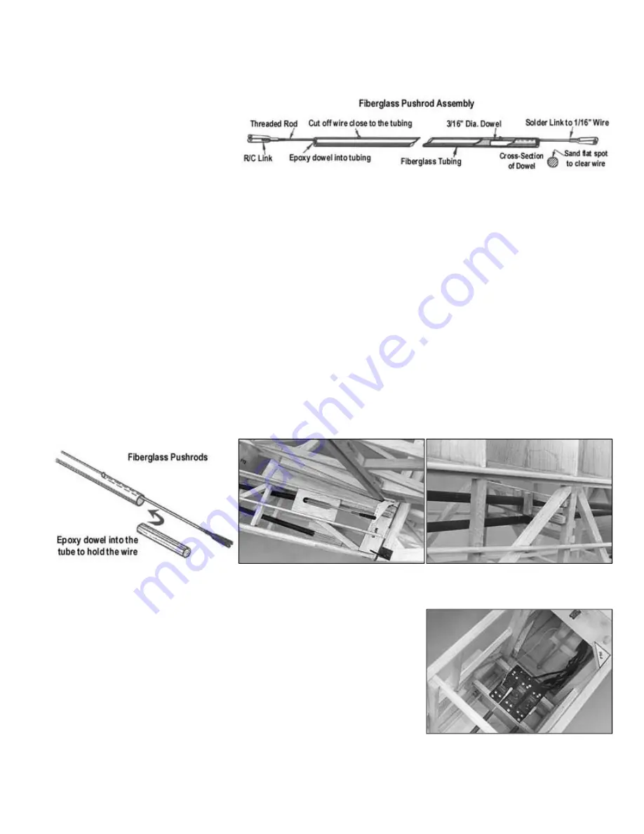
 

Pushrod Assembly

 
Materials are supplied for building 
fiberglass pushrods to link the elevator 
and rudder servos to their control horns. 
Make the control surface ends of the 
pushrods first.

 
Put a 90° bend in the unthreaded end of the 4-40x8" threaded rod. Drill a 3/32" diameter hole 2" from the end of the 
fiberglass pushrod tube. Slide the 4-40 rod into the tube, sticking the 90° bend through the hole.
 
Sand a flat spot on one side of the 3/16"x2-1/2" dowel until it can be squeezed into the tube alongside the 4-40 rod. When 
you get the fit right, final assemble the parts into the tubes with epoxy glue. It should not be necessary to put any bends in 
the 4-40 wires of either the elevator or rudder pushrod to get them to feed through the fuselage and hook up to the control 
horns. It's a pretty straight shot if your servos are positioned side by side as shown in a previous photo. However you may 
have to trim out a portion of the diagonal 5/16" sq. main frame balsa under the stab to clear the elevator pushrod wire. 
 
Assemble the servo ends of both pushrods in the same fashion, only use 1/16" dia. x 8" music wire and solder links instead 
of the 4-40 size hardware. After you've got the 1/16" wires and dowels epoxied into the tubes, feed the pushrods back into 
the fuselage and hook up to the control surfaces. Center the 4-40 links on the threads at the tail end. Then measure and 
cut off the 1/16" wires at the front, to the length which will allow the solder links to reach the servo arms. Protect the servos 
with a rag while soldering the links onto the ends of the wires. 
 
Your elevator and rudder pushrods should now be complete and operating freely. Fill in around the 4-40 pushrod wires 
where they exit the fuselage with scrap sheet balsa, glued in flush with the stringers. 
 
Brace the pushrods in the middle (near former F9) with 1/4" sq. scrap balsa to eliminate any possibility of in-flight vibration 
or bowing problems. Criss-cross pieces of 1/4" sq. stick on all four sides of each push rod. Glue them to the 5/16" sq. main 
frame balsa. Have the braces touching the pushrods, but not creating a bind.


Throttle Hookup

 
Either a standard or heavy-duty servo can be used for the throttle control on a .60 
to .90 glow engine. A flexible steel cable pushrod with nylon outer tubing (*, such 
as SIGSH559) is best for hookup of the throttle servo to the carburetor. Follow the 
assembly instructions on the pushrod package.


Battery Pack

 
Due to the larger than normal battery drain from using heavy-duty servos, a 1000 
mah receiver battery pack (*) is recommended. Wrap the battery pack in foam 
rubber (*, such as SIGRF240) held on with rubber bands or masking tape, to 
protect it from engine vibration. Secure it as far forward as possible in the nose 
under the fuel tank.

Summary of Contents for Sigrc47

Page 1: ...that many hours of flight time accumulated in just 12 years it s pretty safe to assume that N32629 was used for flight training during the 1940 s The Cub was sold in 1955 to an A E mechanic who moved it to Mount Pleasant Iowa It remained in Iowa through the 1960 s being used by several different owners for pleasure flying Hazel Sig president of SIG MFG CO purchased N32629 in January of 1968 She fl...

Page 2: ... and Maxey all had different ideas They agreed on the sunburst pattern but according to Hazel Glen wanted it to be red and white Maxey like blue and white and I thought yellow and white would look best As you can see Maxey is the one who actually loaded the spray gun Hazel Sig taxies her rebuilt Clipped Wing Cub out of the hangar for its very first test flight at the Ottumwa Airport in the summer ...

Page 3: ...e would You have to run them fast in level flight in order to have good climb performance We do not recommend converted chain saw type gas engines for this model They tend to vibrate more than a precision made glow engine and are usually too bulky to fit inside the cowling Regardless of what size and type of engine you decide to use strive to keep your Cub as light as possible for best flight perf...

Page 4: ...n the cockpit Building large airplanes requires a large building board For this Cub you will need a board that is at least 18 wide x 72 long It must be perfectly flat and untwisted If you don t have one that big go to the local lumber yard and purchase a door core of at least these dimensions Door cores are normally very straight and true be sure to inspect it before buying and they are not too ex...

Page 5: ...die cut balsa rear fuselage formers F8 F9 F10 and F11 each come in two pieces Glue the halves together at the center F8 F9 and F10 should each be reinforced with a piece of 1 8 x1 4 balsa as shown 2 Fuselage Frame Assembly a Cut the MF 1 MF 2 MF 3 MF 4 and MF 5 pieces from the 5 16 printed balsa sheets Cover the Fuselage Main Frame drawing with wax paper or plastic wrap for protection Using the pr...

Page 6: ...the tail end Let dry i Epoxy 1 8 x1 x6 plywood Landing Gear Block Doublers to the top side of the Grooved Landing Gear Blocks When dry epoxy the blocks in place in the fuselage Make sure that the grooves in the blocks are 5 7 8 apart as shown in the side view fuselage plan j Epoxy the 1 8 x1 x6 plywood Strut Mount Insert in front of the rear Landing Gear Block k Set the fuselage on the Top View pl...

Page 7: ...6 square main frame pieces so the Cabin Wires can enter the slot that is between MF 1 and MF 2 g Trial fit the Cabin Wires in place and rebend them slightly if necessary to get a good fit in your model Take coarse grit sandpaper and sand the wires in the areas where they will be glued into the model structure This will improve glue adhesion When satisfied with the fit epoxy the Cabin Wires into th...

Page 8: ... into the round cavity in the molded nylon Steering Arm Make sure that the set screw hole in the wheel collar is lined up with the hole molded into the steering arm Thread the 4 40 x 3 16 Set Screw round head into the wheel collar 7 8 Insert the top of the Formed Tailwheel Wire thru the Nylon Tailwheel Bearing and secure in place with the Steering Arm Be sure to file or grind a small flat spot on ...

Page 9: ...a sanding block to taper them near the front and the back as shown in the Fuselage Top View f Glue on the 1 8 x1 4 balsa Bottom Corner Stringers Notice in the cross section drawings that these are glued on flat against the main frame not on edge as were the Side Stringers Taper these stringers also aft of F13 to blend into the end of the fuselage g Add 1 8 sheet balsa fill in on the sides of forme...

Page 10: ...gthened by lining the inside with fiberglass cloth stuck down with slow drying epoxy glue or polyester glass resin The first step is to sand the inside of the cowl with 80 grit garnet or similar grained sandpaper Remove as much of the gloss from the plastic as possible Don t worry about scratches in the plastic a rough surface on the inside will help the cloth and glue stick better CAUTION Never u...

Page 11: ... X Acto knife This opening can be left wide open or if you want a more scale appearance you can glue in a piece of plastic window screen wait until after all painting is done o Trim out the Right and Left Dummy Engine Cylinder moldings along the lines shown in the photo Leave a small flange about 1 16 to 1 8 wide along the back of the part where it will match the curvature of the cowl The best pro...

Page 12: ...at the top of the 3 16 Main Gear wire Position this wire carefully before soldering note in the front view on plan plate 4 that the middle bend of this Top Shock Strut wire should contact the middle bend of the Bottom Shock Strut wire so that they can later be bound together by rubber bands for flying The rubber bands will serve as an effective shock absorber e After all the solder joints are cool...

Page 13: ...g order a Pin down the 3 8 x1 2 balsa stabilizer trailing edge b Add the 3 8 x1 2 balsa elevator leading edges and the 3 8 sq spruce elevator joiner Be careful not to glue these parts to the stab trailing edge while gluing them to each other c Fit in Sl A and Sl B d Add printed parts S2 S3 S4 S5 S6 S7 and S8 e Fit in E1 E6 and the 3 8 basswood elevator horn insert f Add printed parts E2 E3 E4 E5 E...

Page 14: ...brace h When dry unpin from the plan and sand the outside edges round i Inlet the bottom of the Rudder to accept the rudder horn Epoxy the horn in place Reinforce the installation with glass cloth and epoxy glue j Install the hinges where shown on the plan Here are two photos of Hazel s full scale Clipped Wing Cub as it looked when it came out of the restoration shop in 1969 ...

Page 15: ...the bellcrank wing cross section drawing d Pin the two 1 4 sq Spruce Bottom Spars in place on the plan e Pin the 1 4 sq balsa Bottom Rear Spar in place Note that this spar is doubled in height between ribs WI to W4 f Pin all of the wing ribs securely in place Use a triangle to make sure that they are perpendicular to the board g Add the 1 4 square Spruce Top Spars Glue all joints securely h Glue i...

Page 16: ...eting pinned down securely absolutely flat on the board s Add the 3 32 x1 1 2 balsa Top Aileron Sheeting Check the location carefully with the aileron cross section drawings t Glue gusset WG 1 in place against rib W3 and inside the trailing edge sheets u Carve and sand the 1 8 Leading Edge flush with the tops of the ribs v Glue and pin in place the 3 32 x3 balsa Top Leading Edge Sheeting Also add ...

Page 17: ...ate adhesives can be used Carefully bend and glue the first strip to WTP Add the other strips one at a time firmly gluing them to each other without gaps f When the laminated edge is dry sand flush with the front of the wing panel and glue on the 3 8 x1 balsa Leading Edge Cap g Cut a small gusset from scrap balsa to go in the corner of the wingtip near the trailing edge Glue on the top side of WTP...

Page 18: ...self plenty of alignment time Follow these steps 1 First coat the back side of the Front Dihedral Brace with glue 2 Use a wire to thoroughly coat with glue the surface of the 3 16 spar webs that the brace will bond to inside the wing panel 3 Run a small bead of glue along the edge of the center section bottom sheeting 4 Then slide the wing panel in place and pin securely 5 Coat the adjoining WA ri...

Page 19: ...ces to wing contour g With a razor saw cut the base off one of the long nylon control horns that are supplied Drill some random glue anchor holes in the top area of the horn h Inlet the bottom leading edge of the aileron to allow the nylon horn to be slid in place alongside the plywood riblet W5A Refer to the aileron cross section drawing to see how far in the horn should be installed Hold the hor...

Page 20: ...lans Trim the blocks supplied roughly to match these three viewpoints Leave them slightly oversize Then glue them in place on the front of former F5 Sand and trim to match the contour of the wing 15 Wing Struts Assembly of the wing struts requires the completed wing and fuselage a Locate the two 1 16 x1 2 x2 aluminum strips supplied for the Fuse Strut Fittings Round all four corners of the strips ...

Page 21: ... Fittings up against the bottom of the wing and mark the locations for the 4 40 mounting bolts onto the ply mounting insert FSM and RSM Take the struts back off Drill holes through the ply inserts and epoxy 4 40 blind nuts in from the inside you ll have to make a small opening in the front spar webbing to get the front blind nuts in h Carve and sand the edges of the struts round See cross section ...

Page 22: ...till have easy access inside the model Once the initial installation has been made and all the bugs are worked out you can take the radio system back out while the painting is being done In spite of some of the things you may have heard or read putting a radio in your 1 4 scale Cub need not be much different than for a smaller model This section describes the control system installations that have...

Page 23: ...e hardware After you ve got the 1 16 wires and dowels epoxied into the tubes feed the pushrods back into the fuselage and hook up to the control surfaces Center the 4 40 links on the threads at the tail end Then measure and cut off the 1 16 wires at the front to the length which will allow the solder links to reach the servo arms Protect the servos with a rag while soldering the links onto the end...

Page 24: ...c wire pivots to the ply pieces Make sure the bellcranks operate freely up to this point A 36 long piece of small 1 8 o d approx nylon tubing is provided Cut it into two 18 long pieces and slide these into the holes you drilled into the wing ribs during the wing panel construction Slide the 1 16 dia music wire pushrods inside the nylon tubes Check for any binding that may be caused by slight misal...

Page 25: ...hrough the rubber stopper 1 for fuel feed and 2 for vents Both vent tubes should curve upwards inside the tank The clunk line on the fuel feed tube must swing freely without hitting the back of the tank If your tank as supplied does not come with silicone tubing for the internal fuel feed line substitute a piece of Sig Heat Proof Silicone Tubing SIGSH290 Large With it installed the tank can be lef...

Page 26: ...long the fabric stuck to the fin bottom rib Let dry between coats 5 Finish sticking down the remainder of the covering piece ot the top of the fin 6 Now repeat the steps to cover the right side of the fin and the fuselage top in the same manner When dry resume following the rest of the written instructions for doped on coverings Be careful when applying the pre color clear dope coats over the enti...

Page 27: ...spraying a coat of Lite Coat clear dope over the entire color scheme to protect the colors from scuffing and to give the entire model a uniform gloss For best results it is not a good idea to try to mix different brands of paint Use SIG products from the start Bottom View Color Scheme 20 Sanding And Painting The Plastic Parts CAUTION Do not try to cover any of the plastic parts with Monokote Cover...

Page 28: ...etting the surface of the model where the decal will be placed with a generous quantity of soapy water solution a little dish soap in water or a commercial cleaner like Sig Blue Magic Model Airplane Cleaner 409 or Fantastic brand cleaners will all work equally well Peel the paper backing sheet completely off the decal being careful not to let the sticky side double over and adhere to itself Place ...

Page 29: ... to bend the plastic around the Braces just glue it to the front edge When satisfied with the fit glue all the edges permanently When dry trim off the excess plastic along the Windshield Braces Two 5 1 2 x17 pieces of clear plastic are provided for the side windows One piece is to cover all the window area on one side of the airplane with no seams Lay the plastic sheets on the fuselage and mark th...

Page 30: ...ow and get the model stopped Taxi it back for a fresh start Never try to hurry the model off the ground by pulling full up elevator just because the model isn t going straight The damage from a premature snap roll on takeoff would be much more severe than anything that could happen on the ground Actually the Cub is one of the easiest taildraggers to takeoff that you ll find Just keep practicing yo...

Page 31: ... ...

Page 32: ... ...

Page 33: ...pm Central Copyright SIG Mfg Co Inc SIG MFG CO INC Montezuma Iowa 50171 0520 LIMIT OF LIABILITY In use of our products Sig Mfg Co s only obligation shall be to replace such quantity of the product proven to be defective User shall determine the suitability of the product for his or her intended use and shall assume all risk and liability in connection therewith ...

Reviews: