


Rev.
6
Oct.18
Proprietary and Confidential - Contents subject to change
259
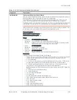
+WIOCFG
(continued)
GPIO Configuration (continued)
Parameters:
<gpio> (Index of I/O port to be configured)
•
Valid range: 1–46. Use AT+WIOCFG? to view supported <gpio> values.
•
Example:
AT+WIOCFG?
+WIOCFG: 2,16,0,0,1,0,0
+WIOCFG: 7,16,0,0,1,0,0
...
The first parameters of each line of output are the valid <gpio> values (e.g. 2, 7, ...).
<func> (I/O port usage)
•
Valid values for Execution format:
•
0—Unallocated
•
4—General GPIO
•
16—Embedded host
•
Valid values for Query format:
•
0—Unallocated
•
2—Antenna Select (applies only to GPIO28–31). GPIO28–GPIO31 can be
allocated for external antenna selection using
.
•
3—External SIM2_DET (applies only to GPIO4, allocated for external SIM2
detection when EXTUIMSWITCHEN customization is enabled)
•
4—General GPIO
•
8—External SIM Switch (applies only to GPIO4,when EXTUIMSWITCHEN
customization is enabled)
•
16—Embedded host
•
26—Wi-Fi/LTE Coexistence control UART (applies only to GPIO35)
<dir> (GPIO direction)
•
0—Input
•
1—Output
<state> (Power-up state for external GPIO configured as an output)
•
0—Output low level
•
1—Output high level
<pull> (Internal pull type for the I/O port)
•
0—No pull
•
1—Pull down
•
2—Keeper
•
3—Pull up
<trigger> (Trigger type for I/O port configured as an input)
•
0—No trigger
•
1—Trigger high
•
2—Trigger low
•
3—Trigger rising
•
4—Trigger falling
<intrvl> (Interval at which the I/O port is checked for the specified trigger (<trig>) level)
•
0—50 ms
•
1—1000 ms
Note: For edge interrupt, the module can only respond one time per 10 ms per GPIO.
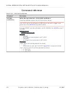
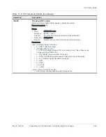
Table 13-2: I/O Command Details (Continued)
Command
Description


