background image

Operation 


6.2 Charging 


VersiCharge AC Wallbox IEC 

48


Operating Instructions, 03/2021, A5E50366109-AA 

Display 

Description 

Action 


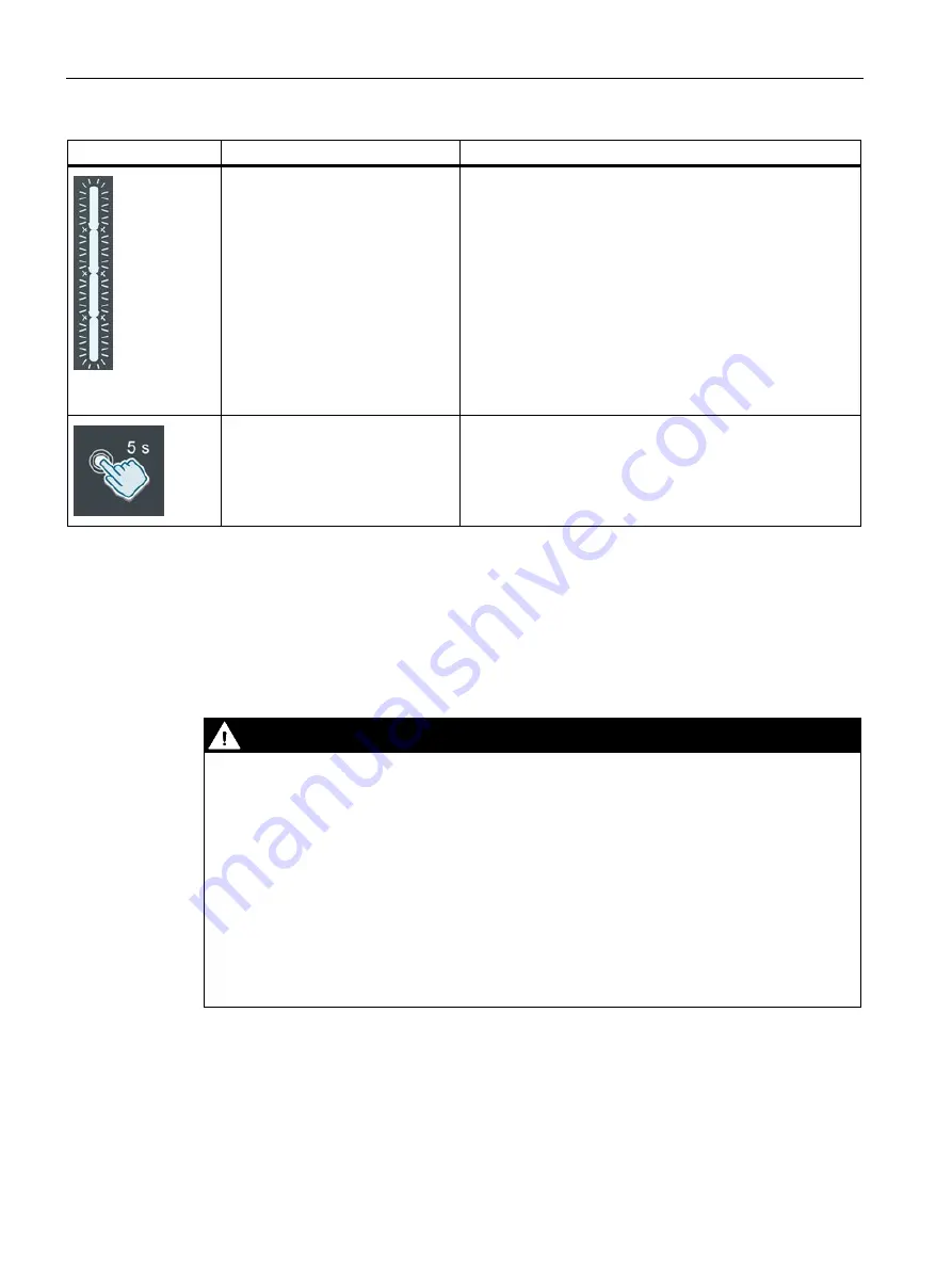
Flashes white 

8 h delay 

Wait until charging process starts. 


Press the Touch button for 5 sec-

onds for maximum charging power 

Power presetting is set to the maximum for the charging 

process. 

Note: Function is inactive with an existing OCPP connection. 


6.2


Charging 

Safety instructions during the charging process  


DANGER 

Risk of electric shock and fire 

Touching live parts may cause electric shock or even death. Defective connectors or cables 

may cause fire. 


Do not kink or squeeze the charging cable. Do not draw the charging cable over sharp 

edges or hot surfaces. 


Do not use the charging station if dangerous damage or tampering is visible. Inform the 

operator. Keep yourself and other persons away from the charging station. 


Grip the power plug to pull the charging cable out of the socket. Do not grip by the cable 

itself. 


Never touch the mains plug with wet hands. 


Do not connect or disconnect any cables during a thunderstorm. 


Summary of Contents for VersiCharge

Page 1: ......

Page 2: ...21 A5E50366109 AA Introduction 1 Safety information 2 Description 3 Mounting Installing Connecting 4 Commissioning 5 Operation 6 Faults 7 Maintenance and service 8 Service Support 9 Disposal 10 Technical specifications 11 Appendix A List of abbreviations B ...

Page 3: ...by personnel qualified for the specific task in accordance with the relevant documentation in particular its warning notices and safety instructions Qualified personnel are those who based on their training and experience are capable of identifying risks and avoiding potential hazards when working with these products systems Proper use of Siemens products Note the following WARNING Siemens product...

Page 4: ... Security information 15 2 7 Safety relevant symbols 16 3 Description 17 3 1 Application 17 3 2 Charging station structure 18 3 3 User interface structure 19 3 4 Scope of delivery 20 3 5 Meter 21 3 6 Identifying the device 21 4 Mounting Installing Connecting 23 4 1 Safety measures during assembly 23 4 2 Preparation before assembly 24 4 3 Assembly procedure 25 4 4 Requirements for the electrical co...

Page 5: ...lt elimination 52 7 2 Error messages 53 8 Maintenance and service 57 8 1 Storage and transport 57 8 2 Cleaning and maintenance 57 8 3 Maintenance 59 8 4 Diagnostic tests 60 8 5 Software updates 60 9 Service Support 61 9 1 Siemens Industry Support 61 10 Disposal 62 10 1 Recycling and disposal 62 11 Technical specifications 63 11 1 Technical specifications 63 A Appendix 65 A 1 Variants available for...

Page 6: ...on WARNING Personal injury and damage to property when the information is not observed Failure to comply with the information in these operating instructions may result in the following Personal injury Material damage Dangerous situations Loss of warranty Follow also vehicle specific operating instructions for the respective vehicle 1 2 Conventions Figures in these operating instructions may devia...

Page 7: ...pen source software contained in it pursuant to the conditions applicable to the product Siemens accepts no liability for the use of the open source software over and above the intended program sequence or for any faults caused by modifications to the software For legal reasons we are obliged to publish the license terms and copyright notices in the original text Please also read the information t...

Page 8: ... on the documentation to that group of people Regulations and guidelines The section Safety indicates hazards and precautions which you must observe during planning assembly installation operation and maintenance You must also adhere to regional and national guidelines and regulations on electrical safety and accident prevention occupational safety Make sure you also follow the following documents...

Page 9: ...Charging electrically operated vehicles in public and semi public areas Charging stations for depots car parks public parking areas and retail Stations for car to go projects Intended use The device serves to charge batteries in fully electric and plug in hybrid electric vehicles The charging station can be used both indoors and outdoors Charge electric vehicles according to IEC 61851 1 and 61851 ...

Page 10: ...hat could cause death or serious injury Risk of explosion and fire Do not store or use flammable liquids that produce flammable fumes such as gasoline or ethanol in the vicinity of the charging station Electrostatic charge or heat generated during charging can ignite explosive and flammable liquids Failure to follow these instructions may result in hazardous situations that could cause death or se...

Page 11: ...ules Failure to follow safety instructions may result in hazardous situations that could cause death or serious injury Safety at the work site When working on roads construction sites and in public areas ensure safety in line with local requirements and regulations To perform the work properly you need to observe Legal specifications On site safety requirements Road traffic conditions Note the fol...

Page 12: ...hese instructions may result in hazardous situations that could cause death or serious injury 2 3 Safety during electrical installation Observe the following points for the electrical installation The electrical connection of the charging unit can only be performed by skilled electricians and can only be carried out at zero current Follow the installation and connection instructions Observe the ap...

Page 13: ... sockets and charging cable Inspect sockets and the charging cable for damage on a regular basis Damaged charging cables endanger safe operation If you detect damage to the charging cable do not commission the cable or stop a running charging process Disconnect the charging cable from the mains without touching it Ensure that the device cannot be switched back on If you notice damage to the chargi...

Page 14: ...ctrical installations apply the following five safety rules 1 Disconnect 2 Secure against reclosing 3 Ensure there is no voltage present 4 Ground and short circuit 5 Cover or shield adjacent live parts Prepare to switch on again after work is finished After finishing and checking the work prepare the restart as follows Inform persons no longer required that the work is completed and no further wor...

Page 15: ...fatal Work on the electrical installation may only be carried out by trained electricians and at zero current Pull the plug not the mains cord Never touch the plug with wet hands Do not perform any installation maintenance or configuration work during a thunderstorm Do not connect the vehicle to or disconnect it from the charging station during a storm Charging cable and socket Defective connector...

Page 16: ...k or the internet if and insofar such a connection is necessary and only when appropriate safety measures e g firewalls and or network segmentation are in place Additional information on industrial safety measures can be found under https www siemens com industrialsecurity Siemens products and solutions undergo continuous development to make them more secure Siemens strongly recommends applying pr...

Page 17: ... ISO 7000 No 0434B Read the information provided in the product documentation ISO 7010 M002 Ensure the device is only installed by an electrically skilled person IEC 60417 No 6182 Adhere to the values for the mechanical load of the device Note that connected mains lines must be designed according to the expected minimum and maxi mum ambient temperature Note that the device must be installed and co...

Page 18: ...f vehicles that require ventilation during the charging process is not possible with the VersiCharge AC Wallbox Functions and properties Charging of electric vehicles in accordance with IEC 61851 1 and 61851 22 Rust free housing made from resistant plastic Connectable charging socket Type 2 or permanently installed charging cable with Type 2 plug according to IEC 62196 Communication via OCPP In co...

Page 19: ...ructure The following figure shows the construction of the VersiCharge AC Wallbox from the front and the back User interface Nameplate Charging socket Connection area protective cover Mount point of wall bracket Entry of supply cable Entry of communication cable SIM card slot MID counter Connecting terminals LAN interface Figure 3 1 Structure ...

Page 20: ...ser interface structure Wi Fi status Remote control Front panel locked Bluetooth status not used Multifunction display for charging status RFID time delay error conditions Touch button RFID reader Status LED Error Status LED Charging active Status LED Power Status LED Vehicle connected Figure 3 2 Charging station structure ...

Page 21: ... components are included with the delivery 1x Wallbox here as symbol drawing for lockable charging socket Type 2 or permanently installed charging cable with Type 2 plug according to IEC 62196 1x wall bracket 6x fastening screw DIN 7996 5x40 6x dowel 8x40 1x securing screw ISO 14583 M3x8 1x ferrite core 1x reducer cable entry 2x RFID card Admin 5x RFID card User ...

Page 22: ...vice Manager See also Technical specifications Page 63 3 6 Identifying the device Nameplate The nameplate is attached on the outside of the device and provides information on the device ID serial number and key connection data Information on the nameplate will help service and support with troubleshooting and procuring matching spare parts For this reason do not remove the rating plate Make sure t...

Page 23: ...ntegrated meter MID compliant H Socket type 2 outlet right J Cable with plug type 2 7 m outlet right 0 IEC 4 RTU TCP Modbus Ethernet WiFi 0 without SIM card slot without mobile wireless connection 3 with SIM card slot default modem GSM LTE G prepared for ISO 15118 upgradable RFID without credit card function A Default color Silver Metallic Pantone 10077 Default cover 0 Child type 1 Parent type wit...

Page 24: ...charging station on a load nearing wall or on a stele intended for this purpose Feed the cables through the base of the charging station DANGER Risk of electric shock due to exposed electrical connections and components Before starting the installation work check that the supply cable has been disconnected from the mains and secured against restart Do not connect the charging station if damage or ...

Page 25: ...licable notes on installation and mounting information The power supply connection is available All power supply connections are de energized and secured against unintentional reconnection Required tools The required tools are not included in the scope of delivery SW 36 open ended wrench Optional cable gland Phillips head screwdriver set Slotted screwdriver set Torx TR screwdriver set Tool set for...

Page 26: ...ill prevent condensation in the charging station If the charging station is to be switched off for a longer period of time you need to provide suitable moisture protection WARNING Risk of accident Risk of accident when the charging station is not secured Do not leave the charging station unattended Place or lay down the charging station and its parts in such a way that the charging station and its...

Page 27: ...the charging station from the package 5 Inspect the charging station for damage Complaints filed after installation will not be accepted 6 Check the package content Page 20 DANGER Risk of electric shock due to exposed electrical connections and components Before starting the installation work check that the supply cable has been disconnected from the mains and secured against restart If damage or ...

Page 28: ... bracket 1 Remove the wall bracket from the charging station Figure 4 1 Removing the wall bracket 2 Align the wall bracket to the mounting surface using a spirit level Use the wall bracket to mark the mounting holes Figure 4 2 Drill picture 3 Put the wall bracket to one side and drill the holes in the wall 4 Insert the dowels in the drilled holes ...

Page 29: ...ure 4 3 Mounting the wall bracket Note When mounting on a column pillar observe the applicable mounting instructions You may need to use different screws and tools 4 4 Requirements for the electrical connection The Wallbox VersiCharge is approved exclusively for fixed installation and has no device for disconnection from the mains The national regulations and standards must be observed during inst...

Page 30: ...ting Instructions 03 2021 A5E50366109 AA 29 4 5 Wiring position Wiring position Hook the charger into the upper and lower notch of the wall bracket Remove protective cover Remove the protective cover of the Wallbox by pressing the two clips upwards to obtain access to the electronics ...

Page 31: ...e load and voltage drop Note Three phase operation The charging station can be operated with 3 phases N PE The specifications can be obtained from the nameplate Page 21 Note Single phase operation The charging station can be operated with 1 phase N PE The specifications can be obtained from the nameplate Page 21 Procedure DANGER Risk of electric shock When connecting the charging unit pay attentio...

Page 32: ...ly cable Note Wire end sleeves with flexible cables When connecting flexible cables use wire end sleeves Cable entry Ferrite core Supply line at the terminal block Figure 4 4 Infeed of VersiCharge Wallbox 8EM1310 0 a Tighten the nuts of the cable gland by hand to ensure a tight seal and strain relief Use the supplied reducer for cables with 9 15 mm outer diameter Check that the seal is sitting cor...

Page 33: ...rician can limit the maximum charging current to the infeed power using the rotary switch The design and protection of the supplying current circuit must be adapted to the set charging current Observe the local regulations connection conditions Setting the current of the VersiCharge unit Figure 4 6 Charging current 1 Open the cover 2 Remove the protective cover 3 Set the desired charging current b...

Page 34: ...ug or Modbus RTU plug after insertion through the sealing insert Mounting the plug before insertion results in damage to the sealing insert 1 Guide the communication cables for Ethernet or Modbus through the wall bracket 2 Make a small hole in the sealing insert using a small screwdriver for example 3 Guide the cables through the sealing insert at the bottom of the device into the Wallbox 4 Mount ...

Page 35: ...shows the connection plugs and DIP switches for the communication cables Note DIP switch settings on device for Modbus RTU setup A8 is the connection resistance switch for the Modbus RTU protocol Set this switch to both ends of the bus connection to ON On all devices in between set this switch to OFF Additional information You can find additional information on the topic of communication here Page...

Page 36: ...cover for the electronics again not in illustration Check that the seal is sitting correctly Make sure that the cables are not crushed or bent when hooking the charger into the wall bracket Lift the charger from the wiring position and close the charging station by placing the charger onto the wall bracket Secure the charging unit against unauthorized opening with the supplied M3x8 screw ...

Page 37: ...hts up on the charging station If the display does not light up on the charging unit check the power supply with a measuring instrument When measuring follow the regional regulations Test run with acceptance Perform the measurements according to DGUV regulation 3 or the comparable regional regulations Concluding work 1 Remove the packing material and protective films 2 Clean the unit if required 3...

Page 38: ...pp on a smartphone To commission multiple devices in a network use the VersiCharge Configurator PC tool You can find additional information in the download area of the respective tools Commissioning with the VersiCharge app To perform the commissioning with the VersiCharge app follow these instructions 1 Install the VersiCharge app from the Google Play Store https play google com store or the Appl...

Page 39: ...et 6 Connect the Wallbox with Siemens Device Management This takes place automatically 7 Assign a descriptive name for the VersiCharge Wallbox 8 Check the settings Only the parent unit is directly connected to the Internet The child units can connect via the shared Wi Fi of the parent unit This is only possible for parent units that are connected to the Internet via a cellular modem or Ethernet Yo...

Page 40: ...tion with Siemens Device Management logging server and OCPP server 20 21 22 80 123 443 514 9019 20000 Communications port for OCPP This depends on the server Wi Fi connection The WLAN interface enables communication of devices with one another as well as communication with the Siemens Device Management The following combinations are possible Wi Fi connection from any VersiCharge device directly to...

Page 41: ... Management system and also to the Siemens OCPP backend if necessary Note that the data connection can incur costs Requirement When working on the SIM card follow the instructions below 1 Disconnect the charging station from the mains 2 Secure it against being switched on again 3 Open the charging station 4 Check the activation 5 Put on ESD clothing and use an ESD grounding wrist strap connected t...

Page 42: ...s Note Safety information The ModBus protocol is an open protocol and it is the responsibility of the installer to ensure the security of the wiring of these connections to prevent tampering Using the Modbus RTU protocol VersiCharge charging stations can act as Modbus devices and make real time data available via the Modbus RTU protocol Higher level Modbus devices connected to the charger e g Modb...

Page 43: ...ust be used to establish a Mod bus RTU connection Baud rate 38400 Parity even Data bits 8 Stop bit 1 5 3 Managing and using RFID The Wallbox supports various authentication methods via OCPP In addition it is possible to save the user IDs of authorized RFID cards in a local preconfigured list You manage the RFID cards via the following channels Modbus controller OCPP based server On the device usin...

Page 44: ...as an integrated RFID reader that is activated ex works The following table lists the supported chip types Table 5 1 Supported chip types Card series Memory Security Supported protocols MIFARE Classic 1K 4K Crypto1 ISO14443A Part 1 3 MIFARE Plus 1K 2K 4K AES Crypto1 ISO14443A Part 1 4 MIFARE DESFire 2K 4K 8K AES 3DES ISO14443A Part 1 4 MIFARE Ultralight 40 48 128 144 None 3DES ISO14443A Part 1 3 ...

Page 45: ... is emitted It is now possible to manage the RFID cards 2 Adding and removing Hold a new User card in front of the RFID reader An acoustic signal is emitted The new User card has been added to the preconfigured list Hold a released User card in front of the RFID reader An acoustic signal is emitted The User card has been removed from the preconfigured list 3 Hold another User card in front of the ...

Page 46: ... Table 6 1 Display Description Action Lights up white Charging station is ready Lights up white Vehicle connected Lights up white Charging in progress Flashes white After switch on the charger will go to Access Point mode Connect PC or mobile device for commissioning Lights up red No Wi Fi reception Check the router ...

Page 47: ...i Fi Read the note about changing the SSID and password in the section Commissioning with PC or mo bile device Page 37 Lights up green Charger is connected to router Strong Wi Fi Flashes blue Attempting to connect to Siemens Device Management Lights up white Ready for operation with success ful connection and registration in Siemens Device Management Lights up blue Access blocked Unlock via RFID O...

Page 48: ...EC Operating Instructions 03 2021 A5E50366109 AA 47 Display Description Action Flashes white 2 h delay Wait until charging process starts Flashes white 4 h delay Wait until charging process starts Flashes white 6 h delay Wait until charging process starts ...

Page 49: ...ging process DANGER Risk of electric shock and fire Touching live parts may cause electric shock or even death Defective connectors or cables may cause fire Do not kink or squeeze the charging cable Do not draw the charging cable over sharp edges or hot surfaces Do not use the charging station if dangerous damage or tampering is visible Inform the operator Keep yourself and other persons away from...

Page 50: ...age to the vehicle or the charging station Basic procedure Connect the vehicle and the charging unit using a suitable cable For a Wallbox with permanently connected cable insert this cable into the socket of the electric vehicle After successful authentication the charging process is started automatically by the vehicle and displayed via the Status LED You have the option of preselecting a time de...

Page 51: ...instructions of the vehicle manufacturer 6 The communication connection to the vehicle is established This process can take some time depending on the connection speed and reaction speed of the backend and vehicle 7 The device locks the plug into the socket The Vehicle connected LED lights up 8 After successfully locking the connector the charging process starts automatically The Charging active L...

Page 52: ...connector from the socket of your electric vehicle 5 Stow away the provided charging cable To do this follow the instructions in the manual for your vehicle Proceed as follows to end the charging process with the operator app 1 Charging point selection Select your vehicle or the charging point by the operator 2 End the charging process 3 Remove the unlocked charging cable 4 Also unplug the connect...

Page 53: ...he event of a fault If the charging station experiences a fault proceed as follows 1 You can find a selection of possible causes of faults in the Error messages Page 53 section 2 If you are unable to rectify the fault yourself contact the operator s service hotline Resetting to factory settings If you need to restore the factory settings proceed as follows 1 Switch off the device close the connect...

Page 54: ...d in the three columns Table 7 1 Fault messages Display Description Solution Lights up white Ground fault DC fault The device is in a fault state Eliminate the fault and then push the touch button to reset Flashes red Some kind of fault has oc curred Turn the supply voltage off and on again Lights up red Fault has occurred Error code 001 Notify Technical Support Lights up red Fault has occurred Er...

Page 55: ...lay Description Solution Flashes red Fault has occurred Error code 003 Notify Technical Support Flashes red Fault has occurred Error code 004 Notify Technical Support Flashes red Fault has occurred Error code 005 Notify Technical Support Flashes red Fault has occurred Error code 006 Notify Technical Support ...

Page 56: ... Display Description Solution Flashes red Fault has occurred Error code 007 Notify Technical Support Flashes red Fault has occurred 008 Notify Technical Support Flashes red Fault has occurred Error code 009 Notify Technical Support Flashes red Fault has occurred Error code 010 Notify Technical Support ...

Page 57: ...t Note Some faults are not caused by the VersiCharge but by EV compatibility or by settings activated in the EV Check the settings in the EV if a fault has occurred The user can define the charging time for example in the settings of the electric vehicle For safety reasons such settings overwrite all commands in the VersiCharge and end the charging process Adapt the settings in your electric vehic...

Page 58: ... Close any transport locks on the cover Avoid shocks and impacts during transport 8 2 Cleaning and maintenance Safety measures Note Before cleaning or service work disconnect the system from the power and ensure it cannot be switched back on To do this deactivate at least all fuses to which the charging station is connected DANGER Risk of electrocution Touching live parts may cause electric shock ...

Page 59: ...crape off stubborn dirt using hard objects Do not use any sharp edged tools Soften paper stickers in advance for easy removal Make sure that water does not get underneath the cover of the charging socket or into the charging plug To ensure optimum quality and functionality clean all charging stations according to agreed intervals Note Use environmentally friendly cleaning agents approved for clean...

Page 60: ...overheating of cables and resulting damage Note Only qualified personnel trained for these activities may perform this work The appendix contains the following lists Installation and maintenance schedule Page 67 Inspecting fixed charging cables Inspect fixed charging cables charging plugs and charging plug holders regularly for the following Damage Wear Contamination Humidity The operator is respo...

Page 61: ...ng Non compliance will void the manufacturer s warranty and invalidate the approvals Remove the meter Only personnel authorized by Siemens may perform work on the meter Non compliance will void the manufacturer s warranty and invalidate the approvals 8 5 Software updates Software updates Siemens makes software updates available as part of ongoing feature enhancements and improvements The software ...

Page 62: ...dustry Online Support https support industry siemens com cs ww on the internet Technical Support Technical Support helps you in the event of technical problems with the product You can reach Technical Support under the following phone number1 49 89 143770229 Opening hours are from 9 am until 5 pm CET Make sure that you have the following information to hand before making the phone call Your contac...

Page 63: ...icable regulations in your country Disposing of the charging station For the environmentally friendly recycling and disposal of your old device contact a certified disposal service for electronic scrap Dispose of the device in accordance with the applicable regulations in your country Waste electrical equipment must not be disposed of as unsorted municipal waste e g household waste The current loc...

Page 64: ... counter Class B 1 Protection Ground fault 30 mA AC 6 mA DC undervoltage overvolt age overcurrent overvoltage category III Residual current circuit breaker RCCB Miniature circuit breaker MCB Not contained Mechanical specifications Mounting Wall or column available as accessories Dimensions H x W x D 446 x 180 x 158 mm Weight 8EM1310 H 4 3 kg 8EM1310 J 7 8 kg Color Silver Metallic Pantone 10077 bla...

Page 65: ... 340 Reader integrated 2 Admin cards 5 User cards in scope of delivery Standards and legal bases EN IEC 61851 1 EN IEC 61851 21 2 EN IEC 60068 2 52 EN IEC 61000 6 1 EN 61000 6 3 EN IEC 61000 6 4 EN 330 330 EN 300 328 EN 301 511 EN 301 893 IEC 62955 A list of order options can be found in section Variants available for order Page 65 in the appendix Times for full charging Charging times depend on m...

Page 66: ...H04 3GA2 7 4 kW 230 V AC Parent without SIM card 8EM1310 2EH04 3GA1 22 kW AC 400 V Child 8EM1310 3EH04 0GA0 22 kW AC 400 V Parent incl SIM card 8EM1310 3EH04 3GA2 22 kW AC 400 V Parent without SIM card 8EM1310 3EH04 3GA1 Variant with 7 m cable 7 4 kW 230 V AC Child 8EM1310 2EJ04 0GA0 7 4 kW 230 V AC Parent incl SIM card 8EM1310 2EJ04 3GA2 7 4 kW 230 V AC Parent without SIM card 8EM1310 2EJ04 3GA1 ...

Page 67: ...7 20 A 5SL6620 7 32 A 5SL6632 7 5SV3344 6 5SV3344 4 Note Additional information on personal protection Follow deviating local regulations According to IEC 61851 1 a 30 mA RCCB Type A is sufficient due to the 6 mA DC fault current monitoring integrated in the Wallbox The listed product recommendations relate to RCCBs with immediate tripping Components with delayed tripping KK01 variant are also sui...

Page 68: ...pment Cleaning Remove dirt dust residue from the device and the usage area Wipe the surfaces with a damp cloth For stubborn stains use a cleaning agent containing alcohol Do not clean the device with a pressure washer Do not use aggressive cleaning agents Check Check the device for the following Cuts damage and soiling Defects and rust Clearly visible signs of faded colors Residue or damage on the...

Page 69: ...le x 15 Visual and functional check for mechanical damage Type 2 plug or lid Housing x x 1 Commissioning with the mobile app PC tool x 10 Check Fault message Backend connection e g Siemens Device Management SIM card x x 5 Cleaning x 5 Check charging sockets or charging cables Charging cable and plug for damage x 2 Measurements acc to DIN VDE e g Insulation measurement Grounding resistance measurem...

Page 70: ...unit Dimension drawing The following graphic shows the general dimensions of the VersiCharge charging unit regardless of the version Figure A 1 Dimension drawing of charging unit Note that the dimensions of the charging unit with permanently installed charging cable and Type 2 plug according to IEC 62196 differ and you will need additional space Figure A 2 Clearances for the wall or adjacent charg...

Page 71: ... marking The declaration of conformity is kept available for the competent authorities at Siemens AG Smart Infrastructure Distribution Systems Mozartstr 31c 91052 Erlangen Germany These files are also available for download on the Siemens Industry Online Support https support industry siemens com cs ww pages under Declaration of Conformity ...

Page 72: ...standardization commission under private law IK Protection class for impact and mechanical stress ISO International Organization for Standardization International standards organization IP International Protection Protection class for solid foreign bodies contact and water MCB Miniature circuit breaker Miniature circuit breaker MID Measurement Instruments Directive OCPP Open Charge Point Protocol ...

Page 73: ... Conformity 70 Error code 53 F Fault 52 Fault messages 53 Function extensions 60 M Messages 53 Mobile wireless connection 40 O Operational messages 45 Overview of variants 65 R Register map command set 42 Required tools 24 Requirements 24 S Safety rules for electrical work 13 Service plan 67 Siemens Care Remote Service 60 Siemens Device Management 37 Status displays 45 Support 61 V VersiCharge Con...

Reviews: