background image

Instalación 

49 

Siemens Building Technologies


Fire Safety & Security Products 


02.2009


ES 

Î


La configuración se guardará. 

9. 

Reinicie el programa. 

10. 

Seleccione las opciones adecuadas en la pestaña 

Banca

. Puede encontrar 

más información al respecto en el Manual de configuración de SISTORE MX. 

8.4.13 Conexión 

de


sistemas de caja registradora 


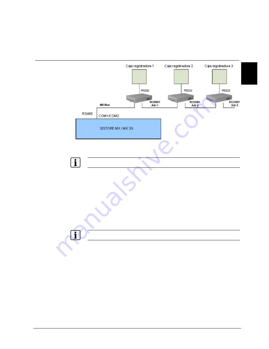
Fig. 30  Vista general del sistema de caja multicanal MX RCI 0601 y caja 

registradora 


Para obtener una descripción más detallada de las conexiones, consulte la sección 6 Descripción de 

SISTORE MX / MX DVD o la 7 Descripción de SISTORE MX 3G/MX 3G DVD. 


1. 

Conecte la(s) caja(s) multicanal MX a la unidad SISTORE (consulte Fig. 30). 

2. 

Conecte las cajas registradoras a RCI 0601. 
Puede encontrar más información al respecto en el manual del usuario de la 

caja multicanal MX RCI 0601. 

3. 

Inicie el software de aplicación SISTORE MX. 

4. 

Cambie a modo configuración. 

5. 

Seleccione la ficha 

Sistema

6. 

Desactive las casillas 

Modo banco

 y 

Cajero automático


Tenga en cuenta que el modo banco y el modo caja registradora se excluyen entre sí. 


7. 

Haga clic en 

Aplicar

Î


La configuración se guardará. 

8. 

Seleccione las opciones adecuadas en la pestaña 

Caja registradora

. Puede 

encontrar más información al respecto en el Manual de configuración de 

SISTORE MX. 

Summary of Contents for SISTORE MX

Page 1: ...ety Security Products SISTORE MX SISTORE MX DVD SISTORE MX 3G SISTORE MX 3G DVD Hybrid Video Recorder Installationshandbuch DE Installation Manual EN Manual de instalación ES Manuel d installation FR Manuale d installazione IT V2 80 ...

Page 2: ......

Page 3: ...Building Technologies Fire Safety Security Products SISTORE MX SISTORE MX DVD SISTORE MX 3G SISTORE MX 3G DVD Hybrid Video Recorder Installationshandbuch DE V2 80 ...

Page 4: ... to use it for any purpose other than for which it was delivered to him Zu diesem Dokument Dieses Dokument enthält Anweisungen zur Installation von SISTORE MX und SISTORE MX 3G Geräten Anweisungen zur Konfiguration finden Sie im Konfigurationshandbuch Anweisungen zur Bedienung finden Sie im Benutzerhandbuch Warenzeichen SISTORE ist ein Warenzeichen der Fire Security Products GmbH Co oHG Microsoft ...

Page 5: ...tzung 20 7 Gerätebeschreibung SISTORE MX 3G MX 3G DVD 21 7 1 Anschlüsse und Anzeigen an der Gerätevorderseite 21 7 2 Anschlüsse an der Geräterückseite 22 7 2 1 Trigger und digitale Eingänge 23 7 2 2 Digitale Ausgänge 23 8 Installation 24 8 1 Rackeinbau 24 8 2 Tischbetrieb 25 8 3 DIP Schalter einstellen SISTORE MX MX DVD 26 8 4 Beispiele für Systemaufbau 28 8 4 1 Bedienpult CKA4810 in Betrieb nehme...

Page 6: ... in Betrieb nehmen 48 8 4 13 Kassensystem in Betrieb nehmen 49 8 4 14 SISTORE Gerät CKA4820 SISTORE RemoteView LAN Kameras 50 9 Software SISTORE Gerät 52 9 1 Software mit virtueller Tastatur bedienen 52 9 2 Software aktualisieren oder reparieren 53 9 3 Software Komponenten nachinstallieren 54 10 Software SISTORE RemoteView 56 10 1 Systemvoraussetzungen 56 10 2 SISTORE RemoteView installieren 57 10...

Page 7: ...pezifischen und ortsüblichen Gesetze Richtlinien und Normen für die Installation den Betrieb und die Entsorgung des Produktes z Beachten Sie zusätzlich die Dokumentationen auf CD Haftungsanspruch z Schließen Sie das Gerät nur an das Versorgungsnetz an wenn es keine Transportschäden aufweist und der Lieferumfang vollständig ist z Nehmen Sie nur Veränderungen am Gerät vor die vom Hersteller genehmig...

Page 8: ...n in diesem Handbuch z Stellen Sie nicht mehrere Geräte aufeinander und stellen Sie keine anderen Gegenstände auf das Gerät Personenschaden Brandgefahr Geräteschaden durch falschen Anschluss an die Spannungsversorgung z Schließen Sie das Gerät nur an eine Versorgungsspannung an die mit der auf dem Gerät angegebenen Betriebsspannung übereinstimmt z Verwenden Sie das Gerät nur mit einem Stromversorg...

Page 9: ...re Security Products GmbH Co oHG 76187 Karlsruhe Deutschland EG Richtlinie 2004 108 EC Elektromagnetische Verträglichkeit Die Konformität mit der EG Richtlinie 2004 108 EC wird nachgewiesen durch die Einhaltung folgender Normen Störaussendung EN 61000 6 4 EN 55022 Kl A Störfestigkeit EN 50130 4 EG Richtlinie 2006 95 EC Niederspannungsrichtlinie Die Konformität mit der EG Richtlinie 2006 95 EC wird...

Page 10: ...d Systemsteuerungen UB inB 5 24 V max 10 mA Digitale Ausgänge 8 Schalt Tastausgänge Schaltflanke und Zeit einstellbar U 5 24 V max 50 mA 16 Schalt Tastausgänge Schaltflanke und Zeit einstellbar U 5 24 V max 50 mA Schnittstellen 2x RS485 1 x LAN 4 x USB 2 0 0 5 A 1 x SCSI 1 x VGA 1 x Audio in 1 x Mic in 1 x Audio out optional SB 0B Schnittstelle für ISDN Maus Tastatur Maus mit USB Anschluss virtuel...

Page 11: ...NTSC 1 120 s 16 7 ms pro Halbbild Geometrische Auflösung PAL 704 x 576 Pixel bei 2 Halbbildern Fields NTSC 704 x 480 Pixel bei 2 Halbbildern Fields Optokoppler Trigger bzw Meldeeingänge Anzahl der Trigger bzw Meldeeingänge 16 32 Triggerflanke Positiv oder negativ Auslösen von Interrupts Ja Spannungsbereich 5 bis 24 V Gleichspannung Eingangsstrom 12 mA typ verpolungssicher Galvanische Trennung Bis ...

Page 12: ...e Tastatur einschaltbar Videonorm PAL Auflösung analog CIF 352 x 288 Pixel 2CIF 704 x 288 Pixel 4CIF 704 x 576 Pixel Auflösung digital LAN Kameras Max 5 Megapixel abhängig vom Kameratyp Kompression M JPEG einstellbar variabel von 10 160 kByte Einblendung von Schrift in das Videobild Max 16 Zeichen Schrift und Hintergrundfarbe Frei wählbar Speichermedien intern Max 4 Festplatten SATA jeweils max 1 ...

Page 13: ...76 Pixel bei 2 Halbbildern Fields Optokoppler Trigger bzw Meldeeingänge Anzahl der Trigger bzw Meldeeingänge 16 Triggerflanke Positiv oder negativ Auslösen von Interrupts Ja Schaltspannung 5 V 10 Schaltstrom Max 5 mA Digitale Eingänge Anzahl digitaler Eingänge 4 Auslösen von Interrupts Nein Digitale Ausgänge Anzahl digitaler Ausgänge 4 Ausgangsstrom 50 mA max Sicherung reversibel Galvanische Trenn...

Page 14: ...gital ca 11 0 kg Mit DVD SISTORE MX 3204 250 150 DVD S24245 F5085 A1 Hybridrekorder 4 Analogkameras 32 LAN Kameras 250 GB 50 B s Analog 100 B s Digital mit DVD ca 11 0 kg SISTORE MX 3208 250 200 DVD S24245 F5085 A3 Hybridrekorder 8 Analogkameras 32 LAN Kameras 250 GB 100 B s Analog 100 B s Digital mit DVD ca 11 0 kg SISTORE MX 3216 500 200 DVD S24245 F5085 A5 Hybridrekorder 16 Analogkameras 32 LAN...

Page 15: ...angsmodul 8 Kanäle mit Optokopplerfunktion USBREL8 2GF4811 8CG USB Ausgangsmodul 8 Kanäle mit Relaisfunktion USBOPTOREL16 2GF4811 8CJ USB Ein und Ausgangsmodule mit 16 Opto Inputs und 16 Relais Outputs USB ISDN Modul 2GF4811 8FC Für den Einsatz am SISTORE MX 0 8 kg SISTORE MX USB Mouse A5Q00009353 Als Ersatzgerät SISTORE MX USB Keyboard A5Q00009346 Für SISTORE MX ohne Tastatur Externer USB DVD Bre...

Page 16: ...Nr Bezeichnung Gewicht 19 Einbausatz für SISTORE MX CX C24245 A12 D2 Befestigungsmaterial zum Einbau in 19 Rack 4 0 kg MX Multichannel Box GAA ATM S24245 F5092 A1 Für den Anschluss von Geldausgabeautomaten Kassen oder Zutrittskontrollen 1 2 kg USBOBTO8 2GF4811 8CH USB Eingangsmodul 8 Kanäle mit Optokopplerfunktion USBREL8 2GF4811 8CG USB Ausgangsmodul 8 Kanäle mit Relaisfunktion USBOPTOREL16 2GF48...

Page 17: ...ler bestellen 5 Lieferumfang SISTORE MX MX DVD z SISTORE Gerät z Maus z Netzkabel z 8 x Anschlussstecker Digital I O SISTORE MX 3204 z 14 x Anschlussstecker Digital I O SISTORE MX 3208 3232 z Aktivierungsformular z CD mit der Anwendungssoftware SISTORE MX und kompletter Dokumentation z Installationshandbuch SISTORE MX 3G MX 3G DVD z SISTORE Gerät z Maus z Netzkabel z 2 x 8 poliger Anschlussstecker...

Page 18: ...nd Stromversorgung Gerät in Betrieb 2 Error Gelb leuchtend Fehler Alarm Initialisierung Überhitzung 3 Camera Gelb leuchtend Kameraausfall 4 Recording Rot leuchtend Aufnahme 5 Hard Disk Grün blinkend Zugriff auf interne Festplatte n Anschlüsse an der Gerätevorderseite 6 USB Anschluss von 2 USB fähigen Geräten z B Tastatur Maus Backup Festplatte DVD Brenner Achtung Der Betrieb von externen USB Festp...

Page 19: ...B fähigen Geräten z B USB ISDN Modem Drucker Maus Tastatur DVD Brenner Achtung Der Betrieb von externen USB Festplatten als Speichererweiterung ist aus technischen Gründen nicht erlaubt 7 COM 1 COM 2 RS485 Anschluss zur Ansteuerung von Schwenk Neige Kameras Bediengerät CKA48xx oder MX Multi Channel Box 8 VGA Zum Anschluss eines Monitors z B CTMC 15 17 19 9 L out Anschluss von handelsüblichen Lauts...

Page 20: ...DN Modem Drucker Maus Tastatur DVD Brenner Achtung Der Betrieb von externen USB Festplatten als Speichererweiterung ist aus technischen Gründen nicht erlaubt 7 COM 1 COM 2 RS485 Anschluss zur Ansteuerung von Schwenk Neige Kameras Bediengerät CKA48xx oder MX Multi Channel Box 8 VGA Zum Anschluss eines Monitors z B CTMC 15 17 19 9 L out Anschluss von handelsüblichen Lautsprechern oder Kopfhörern 10 ...

Page 21: ...öst werden soll können Sie mit der Software SISTORE RemoteView und SISTORE MX auswählen Eingangsbeschaltungen der Optokoppler Optokoppler U1 1K2 RV 5 24 V Digital In Abb 4 Optokoppler Eingangsbeschaltung Pinbelegung als Beispiel Die 8 digitalen Eingänge können Sie zur Steuerung externer Ereignisse benutzen 6 2 4 Digitale Ausgänge Die Ausgänge schalten einen angeschlossenen Verbraucher gegen Masse ...

Page 22: ...efahren Î Nach ausreichender Abkühlung min 2 Stunden wird das Gerät automatisch hochgefahren Mögliche Ursachen z Mindestabstand von 85 mm an der linken und rechten Seite des Gerätes ist nicht eingehalten z Umgebungstemperatur ist zu hoch Siehe Kap 71H3 72HTechnische Daten Maßnahmen 1 Ziehen Sie den Netzstecker und lassen Sie das Gerät abkühlen 2 Warten Sie min 2 Stunden bis das Gerät abgekühlt ist...

Page 23: ...zw zu niedriger Temperatur Wenn die Betriebstemperatur des Gerätes zu hoch bzw zu niedrig ist wird das Gerät automatisch herunter gefahren und befindet sich in der Wartezeit Nach Ablauf der Wartezeit 6 min wird die Temperatur erneut überprüft Wenn die Temperatur wieder im Normalbereich liegt wird das Gerät automatisch gestartet Wenn die Temperatur immer noch zu hoch bzw zu niedrig ist kann das Ger...

Page 24: ... Video Input LOOP 16 Videoschleifen Anschluss von 75 Ohm BNC Kabel 5 Audio 16 Audio Eingänge noch nicht unterstützt 4 Audio Ausgänge noch nicht unterstützt 6 Alarm 16 Alarm Eingänge 7 Digital 4 Digitale Eingänge 4 Digitale Ausgänge 8 RS485 2 Anschlüsse Anschlüsse 3 und 4 belegt Transparente Datenkanäle zur Steuerung von Schwenk Neige Kameras Bediengerät CKA48xx oder MX Multi Channel Box Hinweis Di...

Page 25: ...riggerflanke auf die ein Triggerereignis ausgelöst werden soll können Sie mit der Software SISTORE RemoteView und SISTORE MX auswählen Eingangsbeschaltungen der Optokoppler _ RV 1K2 Digital In Optokoppler UB Abb 8 Optokoppler Eingangsbeschaltung Pinbelegung als Beispiel Die 4 digitalen Eingänge können Sie zur Steuerung externer Ereignisse benutzen 7 2 2 Digitale Ausgänge Die Ausgänge schalten eine...

Page 26: ...e Gehäusefüße am Gerät mittels Schraubendreher 2 Entfernen Sie die beiden vorderen Deckelbefestigungsschrauben M4x6 zunächst an einer Seite des Gerätes 3 Schrauben Sie einen der im Einbausatz enthaltenen Eckwinkel mit den Schrauben M4x12 an der Geräteseite an vgl 75HAbb 10 VORSICHT Verwenden Sie nur die im Einbausatz enthaltenen Schrauben M4X12 keine längeren Schrauben Ansonsten kann das Gerät inn...

Page 27: ...pfschraube ISO 7045 M6x18 H ZN 7 Scheibe DIN 125 A 6 4 PA 8 Käfigmutter M6 mit Kontaktierung 8 2 Tischbetrieb WICHTIG Überhitzung des Gerätes Bei Überhitzung wird das Gerät automatisch herunter gefahren 1 Prüfen Sie den Mindestabstand von 85 mm an den Seiten des Gerätes 2 Prüfen Sie die Umgebungsbedingungen Siehe Kap 77H3 78HTechnische Daten 3 Stapeln Sie max 3 Geräte aufeinander 4 Legen Sie keine...

Page 28: ...ale müssen die DIP Schalter auf off gestellt sein WICHTIG Fehlfunktionen des SISTORE Gerätes durch fehlende Terminierung Durch fehlende Terminierung kann sich die Bildqualität verschlechtern z Nehmen Sie die Terminierung immer am Leitungsende vor 1 bis 8 75 Ohm Terminierung 1 75 Ohm Terminierung Dipsw Belegung 1 VIN13 2 VIN14 3 VIN15 4 VIN16 2 75 Ohm Terminierung Dipsw Belegung 1 VIN29 2 VIN30 3 V...

Page 29: ...psw Belegung 1 VIN25 2 VIN26 3 VIN27 4 VIN28 5 75 Ohm Terminierung Dipsw Belegung 1 VIN5 2 VIN6 3 VIN7 4 VIN8 6 75 Ohm Terminierung Dipsw Belegung 1 VIN21 2 VIN22 3 VIN23 4 VIN24 7 75 Ohm Terminierung Dipsw Belegung 1 VIN1 2 VIN2 3 VIN3 4 VIN4 8 75 Ohm Terminierung Dipsw Belegung 1 VIN17 2 VIN18 3 VIN19 4 VIN20 ...

Page 30: ...ung zeigt einen möglichen Systemaufbau mit einem SISTORE Gerät Weitere konkrete Beispiele finden Sie in den nachfolgenden Kapiteln Abb 12 Systemübersicht SISTORE Gerät Weitere Informationen zu den Anschlüssen finden Sie in Kap 79H6 80HGerätebeschreibung SISTORE MX MX DVD oder Kap 81H7 82HGerätebeschreibung SISTORE MX 3G MX 3G DVD ...

Page 31: ... SISTORE Gerät den Konverter an vgl 89HAbb 13 Siehe Kap 90H4 91HBestellangaben 2 Parametrieren Sie den COM1A Anschluss am Bedienpult für die Nutzung als RS232 Schnittstelle Weitere Informationen hierzu finden Sie in der Bedienungsanleitung des Bedienpults CKA4810 und der Konverter 3 Starten Sie die Anwendungssoftware SISTORE MX 4 Wechseln Sie in den Konfigurationsmodus 5 Wählen Sie das Register Sy...

Page 32: ...HSoftware Komponenten nachinstallieren 1 Schließen Sie das Bedienpult CKA4810 an den Client PC an vgl 98HAbb 14 2 Parametrieren Sie den COM1A Anschluss am Bedienpult für die Nutzung als RS232 Schnittstelle Weitere Informationen hierzu finden Sie in der Bedienungsanleitung des Bedienpults CKA4810 und der Konverter 3 Starten Sie die Anwendungssoftware SISTORE RemoteView 4 Wechseln Sie in den Konfigu...

Page 33: ...t installiert und das Symbol wird in der Taskleiste angezeigt Siehe Kap 103H9 3 104HSoftware Komponenten nachinstallieren 1 Schließen Sie das Bedienpult CKA4820 an das SISTORE Gerät an vgl 105HAbb 15 2 Parametrieren Sie den COM1B Anschluss am Bedienpult für die Nutzung als RS485 Schnittstelle Weitere Informationen hierzu finden Sie in der Bedienungsanleitung des Bedienpults 3 Starten Sie die Anwen...

Page 34: ...te View Abb 16 Systemübersicht TSISTORE RemoteViewT TCKA4820 Weitere Informationen zu den Anschlüssen finden Sie in Kap 108H6 109HGerätebeschreibung SISTORE MX MX DVD oder Kap 110H7 111HGerätebeschreibung SISTORE MX 3G MX 3G DVD Voraussetzung z Der CKA Treiber ist installiert und das Symbol wird in der Taskleiste angezeigt Siehe Kap 112H9 3 113HSoftware Komponenten nachinstallieren 1 Schließen Sie...

Page 35: ...men ShuttlePRO2 über die Firma Contour Design Ltd bezogen werden www contourdesign com Das Multimedia Control Panel wurde in SISTORE MX integriert und getestet Die Siemens Building Technologies Fire Security Products GmbH Co oHG kann jedoch keinen fehlerfreien Betrieb des Multimedia Control Panels garantieren und übernimmt hierfür keinen Support Bitte wenden Sie sich bei Problemen mit diesem Produ...

Page 36: ...ebeschreibung SISTORE MX 3G MX 3G DVD Software für Multimedia Control Panel installieren 1 Schließen Sie das Multimedia Control Panel an einen USB Steckplatz des SISTORE Gerätes bzw des Client PCs an vgl 121HAbb 17 bzw 122HAbb 18 2 Legen Sie die vom Hersteller mitgelieferte CD in das CD DVD Laufwerk Î Die CD startet automatisch 3 Falls die CD nicht automatisch startet doppelklicken Sie die Datei A...

Page 37: ...ion 35 Siemens Building Technologies Fire Safety Security Products 02 2009 DE Î Folgendes Dialogfenster wird geöffnet 5 Klicken Sie auf LAUNCH SETUP Î Folgendes Dialogfenster wird geöffnet 6 Klicken Sie auf Next ...

Page 38: ...9 Î Folgendes Dialogfenster wird geöffnet 7 Markieren Sie das Kontrollkästchen Yes I agree with all the terms of this license agreement 8 Klicken Sie auf Next Î Folgendes Dialogfenster wird geöffnet 9 Klicken Sie auf Next um die Software im vorgeschlagenen Verzeichnis zu installieren ...

Page 39: ...ter wird geöffnet 10 Klicken Sie auf Next Î Die Software wird installiert Î Folgendes Dialogfenster wird geöffnet 11 Markieren Sie das Kontrollkästchen Open the Contour Control Panel 12 Klicken Sie auf Finish Î Die Software ist installiert Î Das Dialogfenster Contour Shuttle Device Configuration wird geöffnet ...

Page 40: ... Fire Safety Security Products 02 2009 Multimedia Control Panel konfigurieren Abb 19 Contour Shuttle Device Configuration 1 Klicken Sie auf Options Î Folgendes Kontextmenü wird geöffnet 2 Klicken Sie im Kontextmenü auf den Eintrag Import settings ...

Page 41: ...f bzw SISTORE MX RemoteView pref 5 Klicken Sie auf Apply 6 Wenn Sie das Multimedia Control Panel auch im SISTORE Player verwenden möchten führen Sie die Schritte 13 bis 17 erneut aus und importieren Sie die Datei SISTOREPlayer pref 7 Klicken Sie auf OK Î Das Multimedia Control Panel ist betriebsbereit Informationen zur Bedienung der Anwendungssoftware SISTORE MX SISTORE RemoteView und SISTORE Play...

Page 42: ... Anschlüssen finden Sie in Kap 123H6 124HGerätebeschreibung SISTORE MX MX DVD oder Kap 125H7 126HGerätebeschreibung SISTORE MX 3G MX 3G DVD 1 Installieren Sie die Siemens LAN Kamera CCIx1345 Weitere Informationen hierzu finden Sie im Installationshandbuch der Kamera 2 Konfigurieren Sie die Alarmaufschaltung der Siemens LAN Kamera CCIx1345 Weitere Informationen hierzu finden Sie im Konfigurationsha...

Page 43: ...nungsanleitung des Domes 2 Starten Sie die Anwendungssoftware SISTORE MX 3 Wechseln Sie in den Konfigurationsmodus 4 Markieren Sie im Register Kameras das Kontrollkästchen Schwenk Neige Steuerung 5 Wählen Sie aus dem ersten Listenfeld den Kameratyp aus 6 Wählen Sie aus dem zweiten Listenfeld die Schnittstelle aus 7 Klicken Sie auf Übernehmen Î Die Schnittstelle für die Dome Kamera ist aktiviert We...

Page 44: ...der Bedienungsanleitung des Domes und des Bedienpults 2 Starten Sie die Anwendungssoftware SISTORE MX 3 Wechseln Sie in den Konfigurationsmodus 4 Wählen Sie das Register System 5 Markieren Sie das Kontrollkästchen Bedien Panel Weitere Informationen hierzu finden Sie im Konfigurationshandbuch SISTORE MX Î Die Schnittstelle für das Bedienpult ist aktiviert 6 Wählen Sie das Register Kameras 7 Markier...

Page 45: ...ra an das SISTORE Gerät an vgl 144HAbb 23 Weitere Informationen hierzu finden Sie in den Bedienungsanleitungen des Schwenk Neigeantriebs des Antriebsgerätes und der Kamera 3 Starten Sie die Anwendungssoftware SISTORE MX 4 Wechseln Sie in den Konfigurationsmodus 5 Wählen Sie das Register Kameras 6 Markieren Sie das Kontrollkästchen Schwenk Neige Steuerung 7 Wählen Sie aus dem ersten Listenfeld den ...

Page 46: ...der Kamera 3 Starten Sie die Anwendungssoftware SISTORE MX 4 Wechseln Sie in den Konfigurationsmodus 5 Wählen Sie das Register Kameras 6 Markieren Sie das Kontrollkästchen Schwenk Neige Steuerung 7 Wählen Sie aus dem ersten Listenfeld den Kameratyp aus 8 Wählen Sie aus dem zweiten Listenfeld die Schnittstelle aus 9 Klicken Sie auf Übernehmen Î Die Schnittstelle für die Kamera ist aktiviert Weitere...

Page 47: ...D2417 in Betrieb nehmen SISTORE MX MX 3G RS485 CDCD2417 CDCD2417 Abb 26 Systemübersicht Steuereinheit CDCD2417 Weitere Informationen zu den Anschlüssen finden Sie in Kap 156H6 157HGerätebeschreibung SISTORE MX MX DVD oder Kap 158H7 159HGerätebeschreibung SISTORE MX 3G MX 3G DVD 1 Schließen Sie die Schwenk Neigeantriebe über die Steuereinheit CDCD2417 an den RS485 Anschluss COM2 des SISTORE Gerätes...

Page 48: ...an vgl 165HAbb 27 2 Schließen Sie die GAA an die MX Multi Channel Box RCI 0601an Weitere Informationen hierzu finden Sie im Benutzerhandbuch MX Multi Channel Box RCI 0601 3 Starten Sie die Anwendungssoftware SISTORE MX 4 Wechseln Sie in den Konfigurationsmodus 5 Wählen Sie das Register System 6 Markieren Sie die Kontrollkästchen Bank Betrieb und GAA Betrieb Beachten Sie dass Bank und Kassenbetrieb...

Page 49: ...as SISTORE Gerät an vgl 170HAbb 28 2 Schließen Sie den Zutrittsleser an die MX Multi Channel Box RCI 0601 an Weitere Informationen hierzu finden Sie im Benutzerhandbuch MX Multi Channel Box RCI 0601 3 Starten Sie die Anwendungssoftware SISTORE MX 4 Wechseln Sie in den Konfigurationsmodus 5 Wählen Sie das Register System 6 Markieren Sie die Kontrollkästchen Bank Betrieb und GAA Betrieb 7 Klicken Si...

Page 50: ...Schließen Sie das Interface an das SISTORE Gerät an vgl 175HAbb 29 Hierzu benötigen Sie den Konverter 485SD9R Fa B B ein 9 pol Kabel SubD Stecker Stecker Verbindung 2 3 3 2 und ein Null Modem Kabel SubD Stecker Stecker Verbindungen 2 3 3 2 4 6 5 5 6 4 7 8 8 7 2 Verbinden Sie Pin 7 des SubD Anschlusses über einen 81 Ohm Widerstand mit 12 V Siehe nachfolgende Abbildung 1 Pin 7 2 12 V 3 Schließen Sie...

Page 51: ...bung SISTORE MX 3G MX 3G DVD 1 Schließen Sie die Multi Channel Box en an das SISTORE Gerät an vgl 180HAbb 30 2 Schließen Sie die Kassen an das RCI0601 an Weitere Informationen hierzu finden Sie im Benutzerhandbuch MX Multi Channel Box RCI 0601 3 Starten Sie die Anwendungssoftware SISTORE MX 4 Wechseln Sie in den Konfigurationsmodus 5 Wählen Sie das Register System 6 Deaktivieren Sie die Kontrollkä...

Page 52: ...stalliert und das Symbol wird in der Taskleiste angezeigt Siehe Kap 185H9 3 186HSoftware Komponenten nachinstallieren 1 Schließen Sie das Bedienpult CKA4820 an das SISTORE Gerät an vgl 187HAbb 31 2 Parametrieren Sie den COM1B Anschluss am Bedienpult für die Nutzung als RS485 Schnittstelle Weitere Informationen hierzu finden Sie in der Bedienungsanleitung des Bedienpults 3 Starten Sie die Anwendung...

Page 53: ...figuration CKA4820 z Protokoll SIMATRIX RS232 oder SIEMENS IVM z Baudrate 9600 z Parität keine Falls Sie das Bedienpult CKA4820 über die interne COM1A Schnittstelle an ein SISTORE Gerät anschließen wollen müssen Sie den Schnittstellenkonverter RS232C RS485 in die Verbindungsleitung einbauen vgl 188HAbb 13 ...

Page 54: ...E Gerät zu installieren z TREND MICRO TM Office Scan TM z McAfee Security Center Beachten Sie dabei z Die Virenscanner sind nicht im Lieferumfang enthalten z Die CPU Auslastung des Gesamtsystems wird erhöht WICHTIG Datenverlust durch Virenscan Wenn Sie einen aktiven Virenscan durchführen kann es zu einem Aufzeichnungs Stop und dadurch zu Datenverlust kommen z Führen Sie einen Virenscan nur durch w...

Page 55: ...MX startet automatisch 3 Klicken Sie das Login Symbol Î Die virtuelle Tastatur wird automatisch geöffnet 4 Geben Sie das Passwort durch Klicken der jeweiligen Buchstaben und Zeichen auf der virtuellen Tastatur ein 5 Klicken Sie auf OK Î Das System ist betriebsbereit Die Vorgehensweise gilt auch für alle anderen Eingabefelder des Systems 9 2 Software aktualisieren oder reparieren So gehen Sie vor u...

Page 56: ...z den Parametrierungseinstellungen z der Benutzerverwaltung und z die Aufzeichnungen 9 3 Software Komponenten nachinstallieren WICHTIG Funktionsstörungen durch Fremdsoftware auf dem SISTORE Gerät z Installieren Sie auf dem SISTORE Gerät nur vom Hersteller genehmigte Software Sie können Software Komponenten der Anwendungssoftware SISTORE MX auf dem SISTORE Gerät nachinstallieren 1 Legen Sie die Ins...

Page 57: ...pult CKA4810 oder CKA4820 USB I O Treiber für externes USB Ein und Ausgangsmodul optional siehe Kap 191H4 192HBestellangaben 5 Markieren Sie die entsprechenden Kontrollkästchen 6 Klicken Sie auf Weiter Î Folgendes Dialogfenster wird geöffnet 7 Aktivieren Sie das Optionsfeld Ja Computer jetzt neu starten 8 Klicken Sie auf Fertig stellen Î Die entsprechenden Software Komponenten sind installiert ...

Page 58: ... einem anderen PC installieren z Betriebssystem Windows XP SP2 oder höher oder Windows Vista z Pentium IV mindestens 2 6 GHz bei mehr als 16 Kameras min 3 0 GHz z Min 512 MB RAM Empfehlung 2 GB RAM bei Windows XP Max 2024 MB RAM z Grafikkarte S VGA 1024 x 768 oder 1280 x 1024 16 Bit Farbtiefe 64 MB Grafikspeicher oder mehr z Der Grafikkartentreiber muss die Funktionalität von Direct Draw ab V8 x k...

Page 59: ...torrechten admin user angemeldet z Windows Vista Der Benutzer user ist mit Administratorrechten admin user angemeldet Ist das Betriebssystem entsprechend konfiguriert startet beim Einlegen der CD das Installationsprogramm automatisch 1 Starten Sie die Datei SISTORE_MX_RemoteView_280 exe durch Doppelklick Î Folgendes Dialogfenster wird geöffnet 2 Wählen Sie die gewünschte Sprache aus und klicken Si...

Page 60: ...9 Î Folgendes Dialogfenster wird geöffnet 4 Klicken Sie auf Weiter Î Folgendes Dialogfenster wird geöffnet 5 Wählen Sie die Option RemoteView aus und klicken Sie auf Weiter Î Das Fenster Programmordner auswählen erscheint 6 Behalten Sie den vorgeschlagenen Zielordner bei und klicken Sie auf Weiter ...

Page 61: ...n Neustart ist nicht notwendig SISTORE RemoteView ist ab sofort bedienbereit 10 3 SISTORE RemoteView aktualisieren Voraussetzung z Der Benutzer user ist mindestens mit Hauptbenutzerrechten main user besser mit Administratorrechten admin user angemeldet 1 Führen Sie Datei SISTORE_MX_RemoteView_280 exe aus Î Folgendes Dialogfenster wird geöffnet 2 Aktivieren Sie das Optionsfeld Programm aktualisiere...

Page 62: ...RE RemoteView hat Zugriff auf maximal 960 Kameras z Maximal 64 SISTORE RemoteView können gleichzeitig 1 SISTORE Gerät kontaktieren 12 Entsorgung Alle Elektro und Elektronikgeräte sind getrennt vom allgemeinen Hausmüll über dafür staatlich vorgesehene Stellen zu entsorgen Wenn dieses Symbol eines durchgestrichenen Abfalleimers auf einem Produkt angebracht ist unterliegt dieses Produkt der europäisc...

Page 63: ......

Page 64: ...1 Karlsruhe www buildingtechnologies siemens com 2009 Copyright by Siemens Building Technologies Liefermöglichkeiten und technische Änderungen vorbehalten Gedruckt in der Bundesrepublik Deutschland auf umweltfreundlich chlorfrei gebleichtem Papier Dokument Nr A6V10065207 Ausgabe 13 02 2009 ...

Page 65: ...Building Technologies Fire Safety Security Products SISTORE MX SISTORE MX DVD SISTORE MX 3G SISTORE MX 3G DVD Hybrid Video Recorder Installation Manual EN V2 80 ...

Page 66: ...n authorization nor to use it for any purpose other than for which it was delivered to him About this document This document contains instructions for the installation of SISTORE MX and SISTORE MX 3G units For information on configuration please refer to the Configuration Manual For information on operation please refer to the User Manual Trademarks SISTORE is a trademark of Fire Security Products...

Page 67: ...Description of SISTORE MX 3G MX 3G DVD 21 7 1 Connections und displays on the front side of the device 21 7 2 Connections on the back of the device 22 7 2 1 Trigger and digital inputs 23 7 2 2 Digital outputs 23 8 Installation 24 8 1 Rack installation 24 8 2 Tabletop operation 25 8 3 Setting DIP switches SISTORE MX MX DVD 26 8 4 Examples of system design 28 8 4 1 Connecting control panel CKA4810 2...

Page 68: ...ng cash box systems 49 8 4 14 SISTORE unit CKA4820 SISTORE RemoteView LAN cameras 50 9 Software SISTORE unit 52 9 1 Software operation using the virtual keyboard 52 9 2 Updating or repairing software 53 9 3 Subsequent installation of software components 54 10 Software SISTORE RemoteView 56 10 1 System requirements 56 10 2 Installing SISTORE RemoteView 57 10 3 Updating SISTORE RemoteView 59 10 4 Su...

Page 69: ... standards or regulations concerning installation operation and disposal of the product z Please also read the documentation on the accompanying CD Liability claim z Do not connect the device to the supply network if it is damaged or any parts are missing z Do not make any changes or modifications to the device unless they have been approved by the manufacturer z Use only spare parts and accessori...

Page 70: ...z Do not stack several devices on top of each other and do not place any objects on the device Danger of electrical shock fire hazard damage to the device due to incorrect connection z Connect the device only to power sources with the specified voltage Voltage supply requirements can be found on the rating label of the device z Use the device only in conjunction with a power supply cable that has ...

Page 71: ...Security Products GmbH Co oHG 76187 Karlsruhe Germany European Directive 2004 108 EC Electromagnetic Compatibility Compliance with the European Directive 2004 108 EC has been proven by testing according to the following standards Emitted interference EN 61000 6 4 EN 55022 Class A Interference resistance EN 50130 4 European Directive 2006 95 EC Low Voltage Directive Compliance with the European Dir...

Page 72: ...x 10 mA Digital outputs 8 switch key outputs configurable switching rising or falling edge duration U 5 24 V max 50 mA 16 switch key outputs configurable switching rising or falling edge duration U 5 24 V max 50 mA Interfaces 2x RS485 1 x LAN 4 x USB 2 0 0 5 A 1 x SCSI 1 x VGA 1 x Audio in 1 x Mic in 1 x Audio out optionally SB 0B interface for ISDN Mouse keyboard Mouse with USB connection virtual...

Page 73: ...120 s 16 7 ms per field Geometric resolution PAL 704 x 576 pixels with 2 fields NTSC 704 x 480 pixels with 2 fields Optocoupler Trigger and signal inputs Number of trigger and signal inputs 16 32 Trigger edge Positive or negative Triggering of interrupts Yes Voltage range 5 24 V DC Input current 12 mA typ protected against polarity reversal Electrical isolation Up to 2500 V Digital inputs Number o...

Page 74: ...l Video standard PAL Analog resolution CIF 352 x 288 pixels 2CIF 704 x 288 pixels 4CIF 704 x 576 pixels Digital resolution LAN cameras Max 5 megapixels depending on the camera type Compression M JPEG configurable variable between 10 and 160 KB Text overlay in the video image Max 16 characters Font and background colours Freely selectable Internal storage media Max 4 SATA hard disks 1 TB max each M...

Page 75: ...th 2 fields Optocoupler Trigger and signal inputs Number of trigger and signal inputs 16 Trigger edge Positive or negative Triggering of interrupts Yes Switching voltage 5 V 10 Switching current Max 5 mA Digital inputs Number of digital inputs 4 Triggering of interrupts No Digital outputs Number of digital outputs 4 Output current 50 mA max reversible fuse Electrical isolation Up to 2500 V SISTORE...

Page 76: ... digital approx 11 0 kg With DVD SISTORE MX 3204 250 150 DVD S24245 F5085 A1 Hybrid recorder 4 analog cameras 32 LAN cameras 250 GB 50 ips analog 100 ips digital with DVD approx 11 0 kg SISTORE MX 3208 250 200 DVD S24245 F5085 A3 Hybrid recorder 8 analog cameras 32 LAN cameras 250 GB 100 ips analog 100 ips digital with DVD approx 11 0 kg SISTORE MX 3216 500 200 DVD S24245 F5085 A5 Hybrid recorder ...

Page 77: ...h optocoupler function USBREL8 2GF4811 8CG USB output module 8 channels with relay function USBOPTOREL16 2GF4811 8CJ USB input and output modules with 16 optocoupler inputs and 16 relay outputs USB ISDN module 2GF4811 8FC For use on the SISTORE MX 0 8 kg SISTORE MX USB mouse A5Q00009353 As a replacement device SISTORE MX USB keyboard A5Q00009346 For SISTORE MX without keyboard External USB DVD bur...

Page 78: ...l be found on the rating plate on the bottom of the unit Accessories not included in the delivery Type Part no Designation Weight 19 installation kit for SISTORE MX CX C24245 A12 D2 Mounting equipment for installation in a 19 rack 4 0 kg MX multichannel box GAA ATM S24245 F5092 A1 For connection of cash dispensers cash box or access control systems 1 2 kg USBOBTO8 2GF4811 8CH USB input module 8 ch...

Page 79: ...From STM GmbH please order directly from the manufacturer Multimedia Control Panel ShuttlePRO2 From Contour Design Ltd please order directly from the manufacturer 5 Package contents SISTORE MX MX DVD z SISTORE unit z Mouse z Mains cable z 8 x digital I O connector SISTORE MX 3204 z 14 x digital I O connector SISTORE MX 3208 3232 z Activation form z CD with the SISTORE MX application software and c...

Page 80: ... green Power supply unit in operation 2 Error Lit yellow Error Alarm initializing overheated 3 Camera Lit yellow Loss of video 4 Recording Lit red Recording 5 Hard disk Blinking green Access to internal hard drive s Connections on the front side of the device 6 USB Connection of 2 USB enabled devices e g keyboard mouse backup hard drive DVD burner Please note The operation of external USB hard dri...

Page 81: ...nabled devices e g USB ISDN modem printer mouse keyboard DVD burner Please note The operation of external USB hard drives as a memory expansion is not allowed for technical reasons 7 COM 1 COM 2 RS485 Connection for control of pan tilt cameras CKA48xx control panel or MX multichannel box 8 VGA For connecting a monitor e g CTMC 15 17 19 9 L out Connection of commercially available speakers or headp...

Page 82: ...modem printer mouse keyboard DVD burner Please note The operation of external USB hard drives as a memory expansion is not allowed for technical reasons 7 COM 1 COM 2 RS485 Connection for control of pan tilt cameras CKA48xx control panel or MX multichannel box 8 VGA For connecting a monitor e g CTMC 15 17 19 9 L out Connection of commercially available speakers or headphones 10 L in Connection of ...

Page 83: ...gger edge which is to initiate a trigger event can be selected with the software SISTORE RemoteView and SISTORE MX Input circuitry of the optocoupler Optokoppler U1 1K2 RV 5 24 V Digital In Fig 4 Optocoupler input circuitry example of pin assignment The 8 digital inputs can be used to control external events 6 2 4 Digital outputs The outputs ground a connected consumer All outputs can handle a max...

Page 84: ...own automatically Î When the device has cooled down sufficiently min 2 hours it will boot up automatically Possible causes z The device was not installed with a minimum clearance of 85 mm on both sides z The ambient temperature is too high See Section 71H3 72HTechnical data Measures 1 Pull the power plug and allow the device to cool down 2 Wait for at least 2 hours for the device to cool down 3 Ch...

Page 85: ...n when the temperature is too high or too low When the operating temperature of the unit exceeds or falls below a specific threshold the unit will shut down automatically and switch to waiting mode At the end of the waiting time 6 min the temperature is measured again If the temperature is back to normal the unit will be restarted automatically If the temperature is still too high or too low the u...

Page 86: ...5 Ω BNC cable 4 Video input LOOP 16 loop throughs Connection for 75 Ω BNC cable 5 Audio 16 audio inputs currently not supported 4 audio outputs currently not supported 6 Alarm 16 alarm inputs 7 Digital 4 digital inputs 4 digital outputs 8 RS485 2 ports ports 3 and 4 are used Transparent data channels for control of pan tilt cameras CKA48xx control panel or MX multichannel box NOTE The software int...

Page 87: ... These trigger inputs are edge triggered The trigger edge which is to initiate a trigger event can be selected with the software SISTORE RemoteView and SISTORE MX Input circuitry of the optocoupler _ RV 1K2 Digital In Optokoppler UB Fig 8 Optocoupler input circuitry example of pin assignment The 4 digital inputs can be used to control external events 7 2 2 Digital outputs The outputs ground a conn...

Page 88: ...due to overheating 1 Remove the housing base on the unit with a screwdriver 2 Remove the two front cover attachment screws M4x6 first on one side of the unit 3 Screw one of the corner brackets to the side of the unit with the M4x12 screws see 75HFig 10 CAUTION Use only the M4X12 screws supplied with the installation kit Screws that are too long may cause damage to the device 4 Remove the two front...

Page 89: ...rew ISO 7045 M6x18 H ZN 7 Washer DIN 125 A 6 4 PA 8 Cage nut M6 with contacting 8 2 Tabletop operation IMPORTANT Overheating of the device In case of overheating the device will shut down automatically 1 Check to ensure there is a minimum clearance of 85 mm on both sides of the device 2 Check the ambient conditions See Section 77H3 78HTechnical data 3 You can place up to three devices on top of ea...

Page 90: ...gh the DIP switches must be set to off IMPORTANT Malfunctioning of the SISTORE due to lack of termination If the lines are not terminated correctly the image quality may deteriorate z Termination should always be made at the end of the line 1 to 8 75 Ohm termination 1 75 Ohm termination Dipsw Assignment 1 VIN13 2 VIN14 3 VIN15 4 VIN16 2 75 Ohm termination Dipsw Assignment 1 VIN29 2 VIN30 3 VIN31 4...

Page 91: ... Assignment 1 VIN25 2 VIN26 3 VIN27 4 VIN28 5 75 Ohm termination Dipsw Assignment 1 VIN5 2 VIN6 3 VIN7 4 VIN8 6 75 Ohm termination Dipsw Assignment 1 VIN21 2 VIN22 3 VIN23 4 VIN24 7 75 Ohm termination Dipsw Assignment 1 VIN1 2 VIN2 3 VIN3 4 VIN4 8 75 Ohm termination Dipsw Assignment 1 VIN17 2 VIN18 3 VIN19 4 VIN20 ...

Page 92: ...ws a possible system configuration with one SISTORE unit For further specific examples please refer to the following chapters Fig 12 System overview with SISTORE unit For a more detailed description of the connections please refer to Section 79H6 80HDescription of SISTORE MX MX DVD or Section 81H7 82HDescription of SISTORE MX 3G MX 3G DVD ...

Page 93: ...etween the control panel CKA4810 and the SISTORE unit see 89HFig 13 See Section 90H4 91HDetails for ordering92H 2 Configure the COM1A connection on the control panel for use as an RS232 interface Further information on this can be found in the instruction manuals for the control panel CKA4810 and the converter 3 Start the SISTORE MX application software 4 Switch to configuration mode 5 Select the ...

Page 94: ...k bar See Section 97H9 3 98HSubsequent installation of software components 1 Connect the CKA4810 control panel to the client PC see 99HFig 14 2 Configure the COM1A connection on the control panel for use as an RS232 interface Further information on this can be found in the instruction manuals for the control panel CKA4810 and the converter 3 Start the SISTORE RemoteView application software 4 Swit...

Page 95: ...3G MX 3G DVD Prerequisite z The CKA driver is installed and the icon is displayed in the task bar See Section 104H9 3 105HSubsequent installation of software components 1 Connect the CKA4820 control panel to the SISTORE see 106HFig 15 2 Configure COM1B on the control panel as an RS485 interface Further information on this can be found in the instruction manual for the control panel 3 Start the SIS...

Page 96: ...ote View Fig 16 TSISTORE RemoteViewT TCKA4820 system overview For a more detailed description of the connections please refer to Section 109H6 110HDescription of SISTORE MX MX DVD or Section 111H7 112HDescription of SISTORE MX 3G MX 3G DVD Prerequisite z The CKA driver is installed and the icon is displayed in the task bar See Section 113H9 3 114HSubsequent installation of software components 1 Co...

Page 97: ...Products GmbH Co oHG It can be ordered from Contour Design Ltd www contourdesign com product name ShuttlePRO2 The Multimedia Control Panel has been integrated and tested with SISTORE MX Siemens Building Technologies Fire Security Products GmbH Co oHG can however not guarantee fault free operation of the Multimedia Control Panels and does not provide any support In case of problems with the product...

Page 98: ...ORE MX MX DVD or Section 121H7 122HDescription of SISTORE MX 3G MX 3G DVD Installing the software for the Multimedia Control Panel 1 Connect the Multimedia Control Panel to a USB port on the SISTORE unit or on the client PC see 123HFig 17 and 124HFig 18 2 Place the CD in the CD DVD drive Î The CD will start automatically 3 If the CD does not automatically start double click the file Autorun exe Î ...

Page 99: ...Installation 35 Siemens Building Technologies Fire Safety Security Products 02 2009 EN Î The following dialog box opens 5 Click LAUNCH SETUP Î The following dialog box opens 6 Click Next ...

Page 100: ... Products 02 2009 Î The following dialog box opens 7 Mark the checkbox Yes I agree with all the terms of this license agreement 8 Click Next Î The following dialog box opens 9 Click Next to install the software in the default directory Î The following dialog box opens ...

Page 101: ...ty Products 02 2009 EN 10 Click Next Î The software will be installed Î The following dialog box opens 11 Mark the checkbox Open the Contour Control Panel 12 Click Finish Î The software has been installed Î The Contour Shuttle Device Configuration dialog box appears ...

Page 102: ...Technologies Fire Safety Security Products 02 2009 Configuring the Multimedia Control Panel Fig 19 Contour Shuttle Device Configuration 1 Click Options Î The following context menu will open 2 Select Import settings in the context menu ...

Page 103: ...TORE MX pref or SISTORE MX RemoteView pref 5 Click Apply 6 If you also want to use the Multimedia Control Panel with the SISTORE Player repeat steps 13 to 17 and import the file SISTOREPlayer pref 7 Click OK Î The Multimedia Control Panel is ready for operation Information on the operation of the SISTORE MX SISTORE RemoteView and SISTORE Player application software using the Multimedia Control Pan...

Page 104: ... of the connections please refer to Section 125H6 126HDescription of SISTORE MX MX DVD or Section 127H7 128HDescription of SISTORE MX 3G MX 3G DVD 1 Install the Siemens LAN camera CCIx1345 Further information on this can be found in the installation manual for the camera 2 Configure alarm activation for the Siemens LAN camera CCIx1345 Further information on this can be found in the SISTORE MX Conf...

Page 105: ...urther information on this can be found in the instruction manual for the dome camera 2 Start the SISTORE MX application software 3 Switch to configuration mode 4 Mark the checkbox PTZ in the Cameras tab 5 Choose the camera type from the first list box 6 Choose the interface from the second list box 7 Click Apply Î The interface for the dome camera is enabled Further information on this can be fou...

Page 106: ...me cameras and the control panel to the SISTORE see 140HFig 22 Further information on this can be found in the instruction manuals for the dome camera and the control panel 2 Start the SISTORE MX application software 3 Switch to configuration mode 4 Select the System tab 5 Mark the checkbox CCTV keyboard Further information on this can be found in the SISTORE MX Configuration Manual Î The interfac...

Page 107: ...G DVD 1 Connect the pan and tilt unit to the SISTORE see 145HFig 23 2 Connect the camera to the SISTORE see 146HFig 23 Further information on this can be found in the instruction manuals for the pan and tilt unit the control unit and the camera 3 Start the SISTORE MX application software 4 Switch to configuration mode 5 Select the Cameras tab 6 Mark the checkbox PTZ 7 Choose the camera type from t...

Page 108: ...n and tilt unit the converter and the camera 3 Start the SISTORE MX application software 4 Switch to configuration mode 5 Select the Cameras tab 6 Mark the checkbox PTZ 7 Choose the camera type from the first list box 8 Choose the interface from the second list box 9 Click Apply Î The interface for the camera is enabled Further information on this can be found in the SISTORE MX Configuration Manua...

Page 109: ...ler CDCD2417 SISTORE MX MX 3G RS485 CDCD2417 CDCD2417 Fig 26 Controller CDCD2417 system overview For a more detailed description of the connections please refer to Section 158H6 159HDescription of SISTORE MX MX DVD or Section 160H7 161HDescription of SISTORE MX 3G MX 3G DVD 1 Connect the pan and tilt units via controller CDCD2417 to the RS485 port COM2 of the SISTORE see 162HFig 26 2 Further infor...

Page 110: ...el Box to the SISTORE unit see Fig 27 2 Connect the cash dispensers to the MX Multi Channel Box RCI 0601 Further information on this can be found in the user manual for the MX Multi Channel Box RCI 0601 3 Start the SISTORE MX application software 4 Switch to configuration mode 5 Select the System tab 6 Mark the checkboxes Bank mode and Cash dispenser Please note that banking mode and cash register...

Page 111: ...D 1 Connect the MX Multi Channel Box to the SISTORE see 172HFig 28 2 Connect the access reader to the MX Multi Channel Box RCI 0601 Further information on this can be found in the user manual for the MX Multi Channel Box RCI 0601 3 Start the SISTORE MX application software 4 Switch to configuration mode 5 Select the System tab 6 Mark the checkboxes Bank mode and Cash dispenser 7 Click Apply Î The ...

Page 112: ...VD or Section 175H7 176HDescription of SISTORE MX 3G MX 3G DVD 1 Connect the interface to the SISTORE see 177HFig 29 For this you require the converter 485SD9R B B a 9 pin cable Sub D plug plug connections 2 3 3 2 and a null modem cable Sub D plug plug connections 2 3 3 2 4 6 5 5 6 4 7 8 8 7 2 Connect pin 7 of the Sub D connector through an 81 Ohm resistor to 12 V See the figure below 1 Pin 7 2 12...

Page 113: ...ORE MX MX DVD or Section 7 Description of SISTORE MX 3G MX 3G DVD 1 Connect the MX Multi Channel Box es to the SISTORE unit see Fig 30 2 Connect the cash boxes to the RCI 0601 Further information on this can be found in the user manual for the MX Multi Channel Box RCI 0601 3 Start the SISTORE MX application software 4 Switch to configuration mode 5 Select the System tab 6 Untick the checkboxes Ban...

Page 114: ...D Prerequisite z The CKA driver is installed and the icon is displayed in the task bar See Section 187H9 3 188HSubsequent installation of software components 1 Connect the CKA4820 control panel to the SISTORE see 189HFig 31 2 Configure COM1B on the control panel as an RS485 interface Further information on this can be found in the instruction manual for the control panel 3 Start the SISTORE MX app...

Page 115: ...N CKA4820 interface configuration z Protocol SIMATRIX RS232 or SIEMENS IVM z Baud rate 9600 z Parity None If you want to connect the CKA4820 control panel to a SISTORE via the internal COM1A interface install the RS 232C RS 485 interface converter into the connection line see 190HFig 13 ...

Page 116: ... following virus scanners on the SISTORE unit z TREND MICRO TM Office Scan TM z McAfee Security Center Please note the following z The virus scanners are not included in the delivery z The utilization of the system s CPU will be increased IMPORTANT Data loss due to virus scan If you run an active virus scan the recording process may be stopped resulting in a loss of data z Run the virus scan after...

Page 117: ...tware will be started automatically 3 Click the Login icon Î The virtual keyboard will appear 4 Enter the password by clicking the appropriate letters and characters on the virtual keyboard 5 Click OK Î The system is now ready for operation Entries into all other input fields of the system are made in the same manner 9 2 Updating or repairing software You may have to reinstall or repair the SISTOR...

Page 118: ... containing the user management data and z files containing the recorded sequences 9 3 Subsequent installation of software components IMPORTANT Malfunctioning caused by unauthorized software on the SISTORE unit z Install only software products on the SISTORE that have been approved by the manufacturer Software components of the SISTORE MX application software can be subsequently installed on the S...

Page 119: ... Drivers for CKA4810 or CKA4820 control panels USB I O Drivers for external USB input and output module optional see Section 194H4 195HDetails for ordering196H 5 Mark the appropriate checkbox es 6 Click Next Î The following dialog box opens 7 Select the option Yes I want to restart my computer now 8 Click on Finish Î The selected software component has been installed ...

Page 120: ...s z Operating system Windows XP SP2 or higher or Windows Vista z Pentium IV 2 6 GHz or higher when using more than 16 camera at least 3 0 GHz is required z Min 512 MB RAM recommended 2 GB RAM with Windows XP max 2024 MB RAM z S VGA graphics card 1024 x 768 or 1280 x 1024 16 bit colour depth graphics memory 64 MB or higher z The graphics card driver must fully support Direct Draw functionality V8 x...

Page 121: ...n user or rather admin user rights z Windows Vista To log into the system the user must admin user rights The installation program will start automatically when the CD is inserted if your operating system has the appropriate configuration 1 Launch the file SISTORE_MX_RemoteView_280 exe by double clicking on it Î The following dialog box opens 2 Select the desired language and click OK Î The follow...

Page 122: ...ologies Fire Safety Security Products 02 2009 Î The following dialog box opens 4 Click Next Î The following dialog box opens 5 Select RemoteView and click Next Î The Select program folder dialog box opens 6 Do not change the destination folder Click Next ...

Page 123: ...inish It is not necessary to restart your computer SISTORE RemoteView is immediately ready to be used 10 3 Updating SISTORE RemoteView Prerequisite z To log into the system the user must at least have main user or rather admin user rights 1 Launch the file SISTORE_MX_RemoteView_280 exe Î The following dialog box opens 2 Select the option Update 3 Click Next Î The update will be performed automatic...

Page 124: ... station can access up to 960 cameras z Up to 64 SISTORE RemoteView stations can simultaneously connect to the same SISTORE unit 12 Disposal All electrical and electronic products should be disposed of separately from the municipal waste stream via designated collection facilities appointed by the government or the local authorities This crossed out wheeled bin symbol on the product means the prod...

Page 125: ......

Page 126: ...www buildingtechnologies siemens com 2009 Copyright by Siemens Building Technologies Data and design subject to change without notice Supply subject to availability Printed in the Federal Republic of Germany on environment friendly chlorine free paper Document no A6V10065207 Edition 13 02 2009 ...

Page 127: ...Building Technologies Fire Safety Security Products SISTORE MX SISTORE MX DVD SISTORE MX 3G SISTORE MX 3G DVD Grabadora de vídeo híbrida Manual de instalación ES V2 80 ...

Page 128: ...al entregarle el documento Acerca de este documento En este documento se incluyen las instrucciones para la instalación de las unidades SISTORE MX y SISTORE MX 3G Para obtener información sobre la configuración consulte el Manual de configuración Para obtener información sobre el funcionamiento consulte el Manual de usuario Marcas comerciales SISTORE es una marca comercial de Fire Security Product...

Page 129: ...to 27H20 7 Descripción de SISTORE MX 3G MX 3G DVD 28H21 7 1 Conexiones e indicadores del lado delantero del dispositivo 29H21 7 2 Conexiones de la parte trasera del dispositivo 30H22 7 2 1 Entradas digitales y de activador 31H23 7 2 2 Salidas digitales 32H23 8 Instalación 33H24 8 1 Instalación en rack 34H24 8 2 Funcionamiento de sobremesa 35H25 8 3 Posición de los interruptores DIP SISTORE MX MX D...

Page 130: ...48 8 4 13 Conexión de sistemas de caja registradora 56H49 8 4 14 Unidad SISTORE CKA4820 SISTORE RemoteView cámaras LAN 57H50 9 Software unidad SISTORE 58H52 9 1 Utilización del software con el teclado virtual 59H52 9 2 Actualizar o reparar el software 60H53 9 3 Instalación posterior de componentes de software 61H54 10 Software SISTORE RemoteView 62H56 10 1 Requisitos del sistema 63H56 10 2 Instala...

Page 131: ...d específicas de su país que tengan que ver con la instalación el funcionamiento y la eliminación del producto z Consulte también la documentación del CD incluido Declaración de responsabilidad z No conecte el dispositivo a la red de alimentación si está dañado o faltan piezas z No realice ningún cambio o modificación en el dispositivo a menos que el fabricante los haya aprobado z Utilice sólo pie...

Page 132: ... No apile varios dispositivos y no coloque ningún objeto sobre el dispositivo Peligro de descarga eléctrica incendio o daños en el dispositivo debido a una conexión incorrecta z Conecte el dispositivo sólo a fuentes de corriente con el voltaje especificado En la etiqueta de clasificación del dispositivo pueden leerse los requisitos de suministro de voltaje z Utilice el dispositivo únicamente con u...

Page 133: ...ding Technologies Fire Security Products GmbH Co oHG 76187 Karlsruhe Alemania Directiva europea 2004 108 EC Compatibilidad electromagnética La conformidad con la directiva europea 2004 108 EC ha sido probada según las normas siguientes Interferencia emitida EN 61000 6 4 EN 55022 Clase A Resistencia de la interferencia EN 50130 4 Directiva europea 2006 95 EC De bajo voltaje La conformidad con la di...

Page 134: ...es AND y funciones de control del sistema UB inB 5 24 V 10 mA máx Salidas digitales 8 salidas de interruptor tecla conmutación configurable duración de borde creciente o decreciente U 5 24 V 50 mA máx 16 salidas de interruptor tecla conmutación configurable duración de borde creciente o decreciente U 5 24 V 50 mA máx Interfaces 2x RS485 1 x LAN 4 x USB 2 0 0 5 A 1 x SCSI 1 x VGA 1 x Entrada de aud...

Page 135: ...MHz NTSC 13 5 MHz Conversión A D PAL 1 100 s 20 ms por campo NTSC 1 120 s 16 7 ms por campo Resolución geométrica PAL 704 x 576 píxeles con 2 campos NTSC 704 x 480 píxeles con 2 campos Optoacoplador Entradas de activador y señal Número de entradas de activación y señal 16 32 Borde de activación Positivo o negativo Activación de interrupciones Sí Límites de voltaje 5 24 V CC Entrada de corriente 12...

Page 136: ...ión analógica CIF 352 x 288 píxeles 2CIF 704 x 288 píxeles 4CIF 704 x 576 píxeles Resolución digital cámaras LAN 5 megapíxeles máx en función del tipo de cámara Compresión M JPEG configurable variable entre 10 y 160 KB Superposición de texto en la imagen de vídeo Máx 16 caracteres Colores de fuente y fondo De selección libre Medio de almacenamiento interno Máx 4 discos duros SATA 1 TB máx cada uno...

Page 137: ...adas de activador y señal Número de entradas de activación y señal 16 Borde de activación Positivo o negativo Activación de interrupciones Sí Voltaje de conmutación 5 V 10 Corriente de conmutación 5 mA máx Entradas digitales Número de entradas digitales 4 Activación de interrupciones No Salidas digitales Número de salidas digitales 4 Corriente de salida 50 mA máx fusible reversible Aislamiento elé...

Page 138: ...STORE MX 3204 250 150 DVD S24245 F5085 A1 Grabador híbrido 4 cámaras analógicas 32 cámaras LAN 250 GB 50 ips analógico 100 ips digital con DVD aprox 11 0 kg SISTORE MX 3208 250 200 DVD S24245 F5085 A3 Grabador híbrido 8 cámaras analógicas 32 cámaras LAN 250 GB 100 ips analógico 100 ips digital con DVD aprox 11 0 kg SISTORE MX 3216 500 200 DVD S24245 F5085 A5 Grabador híbrido 16 cámaras analógicas ...

Page 139: ...lo de entrada USB 8 canales con función optoacoplador USBREL8 2GF4811 8CG Módulo de salida USB 8 canales con función relé USBOPTOREL16 2GF4811 8CJ Módulos de entrada y salida USB con 16 entradas de optoacoplador y 16 salidas de relé Módulo RDSI USB 2GF4811 8FC Para su uso en SISTORE MX 0 8 kg Ratón USB SISTORE MX A5Q00009353 Como dispositivo de recambio Teclado USB SISTORE MX A5Q00009346 Para SIST...

Page 140: ...Nombre Peso Kit de instalación de SISTORE de 19 MX CX C24245 A12 D2 Equipo de montaje para instalación en bastidor de 19 4 0 kg Caja multicanal MX GAA ATM S24245 F5092 A1 Para la conexión de cajeros automáticos sistemas de caja registradora o de control de acceso 1 2 kg USBOBTO8 2GF4811 8CH Módulo de entrada USB 8 canales con función optoacoplador USBREL8 2GF4811 8CG Módulo de salida USB 8 canales...

Page 141: ... encargar directamente al fabricante 5 Contenido del paquete SISTORE MX MX DVD z Unidad SISTORE z Ratón z Cable de alimentación z 8 conectores E S digitales SISTORE MX 3204 z 14 conectores E S digitales SISTORE MX 3208 3232 z Formulario de activación z CD con el software de aplicación SISTORE MX y documentación completa z Manual de instalación SISTORE MX 3G MX 3G DVD z Unidad SISTORE z Ratón z Cab...

Page 142: ...onamiento 2 Error Se ilumina en amarillo Error alarma iniciando sobrecalentamiento 3 Camera Se ilumina en amarillo Pérdida de vídeo 4 Recording Se ilumina en rojo Grabación 5 Hard disk Parpadea en verde acceso a los discos duros internos Conexiones de la parte frontal del dispositivo 6 USB Conexión a 2 dispositivos con capacidad USB como teclado ratón unidad de disco duro de copia de seguridad o g...

Page 143: ...lado grabador de DVD Atención por motivos técnicos no se permite el uso de unidades de disco duro USB externas como expansión de memoria 7 COM 1 COM 2 RS485 conexión para controlar cámaras de panorámica inclinación panel de control CKA48xx o caja multicanal MX 8 VGA Para conectar un monitor como por ejemplo el CTMC 15 17 19 9 L out Conexión de altavoces o auriculares disponibles en el mercado 10 L...

Page 144: ...cnicos no se permite el uso de unidades de disco duro USB externas como expansión de memoria 7 COM 1 COM 2 RS485 conexión para controlar cámaras de panorámica inclinación panel de control CKA48xx o caja multicanal MX 8 VGA Para conectar un monitor como por ejemplo el CTMC 15 17 19 9 L out Conexión de altavoces o auriculares disponibles en el mercado 10 L in Conexión de fuentes de audio 11 MIC Cone...

Page 145: ... inicia un evento de activación se puede seleccionar con el software SISTORE RemoteView y SISTORE MX Circuitos de entrada del optoacoplador Optokoppler U1 1K2 RV 5 24 V Digital In Fig 4 Optoacoplador circuitos de entrada asignación de terminal como ejemplo Las 8 entradas digitales se pueden usar para controlar eventos externos 6 2 4 Salidas digitales Las salidas conectan a masa un consumidor conec...

Page 146: ...rará automáticamente Î Cuando el dispositivo se haya enfriado lo suficiente mín 2 horas se iniciará de forma automática Causas posibles z El dispositivo no se ha instalado con un espacio mínimo de 85 mm a ambos lados z La temperatura ambiente es demasiado alta Consulte la sección 71H3 72HDatos técnicos Medidas 1 Desconecte el cable de alimentación y deje que el dispositivo se enfríe 2 Espere al me...

Page 147: ... la temperatura es demasiado alta o baja Cuando la temperatura de funcionamiento de la unidad supera o es inferior a un umbral específico la unidad se apagará automáticamente y cambiará a modo de espera Una vez finalice el tiempo de espera 6 min se volverá a medir la temperatura Si la temperatura se restablece la unidad se reiniciará automáticamente Si ésta sigue siendo demasiado alta o demasiado ...

Page 148: ... Ω 4 Video input LOOP 16 interconexiones Conexión para cable BNC de 75 Ω 5 Audio 16 entradas de audio no se admiten actualmente 4 salidas de audio no se admiten actualmente 6 Alarm 16 entradas de alarma 7 Digital 4 entradas digitales 4 salidas digitales 8 RS485 2 puertos se utilizan los puertos 3 y 4 Canales de datos transparentes para controlar cámaras de panorámica inclinación panel de control C...

Page 149: ...s de activadores se activan por borde El borde de activación que inicia un evento de activación se puede seleccionar con el software SISTORE RemoteView y SISTORE MX Circuitos de entrada del optoacoplador _ RV 1K2 Digital In Optokoppler UB Fig 8 Optoacoplador circuitos de entrada asignación de terminal como ejemplo Las 4 entradas digitales se pueden usar para controlar eventos externos 7 2 2 Salida...

Page 150: ...ntamiento 1 Retire la base de la carcasa de la unidad con un destornillador 2 Retire los dos tornillos de fijación delanteros de la carcasa M4x6 primero en un lado de la unidad 3 Fije uno de los soportes de las esquinas al lado de la unidad con los tornillos M4x12 consulte 75HFig 10 PRECAUCIÓN Utilice únicamente los tornillos M4x12 del kit de instalación Los tornillos demasiado largos pueden dañar...

Page 151: ...lo de cabeza plana ISO 7045 M6x18 H ZN 7 Arandela DIN 125 A 6 4 PA 8 Tuerca fija M6 con contactos 8 2 Funcionamiento de sobremesa IMPORTANTE Sobrecalentamiento del dispositivo En caso de sobrecalentamiento el dispositivo se apaga automáticamente 1 Compruebe que hay un espacio mínimo de 85 mm a ambos lados del dispositivo 2 Compruebe las condiciones ambientales Consulte la sección 77H3 78HDatos téc...

Page 152: ... DIP deben ajustarse en la posición off desactivado IMPORTANTE Mal funcionamiento de la unidad SISTORE por falta de terminación Si las líneas no se han cerrado correctamente la calidad de la imagen puede verse deteriorada z La terminación se debe situar siempre al final de la línea 1 a 8 terminación en 75 ohmios 1 Terminación en 75 ohmios Intdip Asignación 1 VIN13 2 VIN14 3 VIN15 4 VIN16 2 Termina...

Page 153: ... 1 VIN25 2 VIN26 3 VIN27 4 VIN28 5 Terminación en 75 ohmios Intdip Asignación 1 VIN5 2 VIN6 3 VIN7 4 VIN8 6 Terminación en 75 ohmios Intdip Asignación 1 VIN21 2 VIN22 3 VIN23 4 VIN24 7 Terminación en 75 ohmios Intdip Asignación 1 VIN1 2 VIN2 3 VIN3 4 VIN4 8 Terminación en 75 ohmios Intdip Asignación 1 VIN17 2 VIN18 3 VIN19 4 VIN20 ...

Page 154: ...sible configuración del sistema con una unidad SISTORE Para obtener más ejemplos específicos consulte los siguientes capítulos Fig 12 Vista general del sistema con la unidad SISTORE Para obtener una descripción más detallada de las conexiones consulte la sección 79H6 80HDescripción de SISTORE MX MX DVD o la 81H7 82HDescripción de SISTORE MX 3G MX 3G DVD ...

Page 155: ...ontrol CKA4810 y la unidad SISTORE consulte 89HFig 13 Consulte la sección 90H4 91HReferencias de pedido92H 2 Configure la conexión COM1A del panel de control para utilizarla como interfaz RS232 Puede encontrarse más información al respecto en los manuales de instrucciones del panel de control CKA4810 y del convertidor 3 Inicie el software de aplicación SISTORE MX 4 Cambie a modo configuración 5 Se...

Page 156: ... la sección 97H9 3 98HInstalación posterior de componentes de software 1 Conecte el panel de control CKA4810 al PC cliente consulte 99HFig 14 2 Configure la conexión COM1A del panel de control para utilizarla como interfaz RS232 Puede encontrar más información al respecto en los manuales de instrucciones del panel de control CKA4810 y del convertidor 3 Inicie el software de aplicación SISTORE Remo...

Page 157: ...uisito previo z El controlador CKA está instalado y aparece el icono en la barra de tareas Consulte la sección 104H9 3 105HInstalación posterior de componentes de software 1 Conecte el panel de control CKA4820 a la unidad SISTORE consulte 106HFig 15 2 Configure COM1B en el panel de control como interfaz RS485 Puede encontrar más información al respecto en el manual de instrucciones del panel de co...

Page 158: ...Remote View Fig 16 TVista general del sistema SISTORE RemoteViewT TCKA4820 Para obtener una descripción más detallada de las conexiones consulte la sección 109H6 110HDescripción de SISTORE MX MX DVD o la 111H7 112HDescripción de SISTORE MX 3G MX 3G DVD Requisito previo z El controlador CKA está instalado y aparece el icono en la barra de tareas Consulte la sección 113H9 3 114HInstalación posterior...

Page 159: ... GmbH Co oHG Puede solicitarse a Contour Design Ltd www contourdesign com nombre del producto ShuttlePRO2 El Panel de control multimedia se ha integrado y probado con SISTORE MX No obstante Siemens Building Technologies Fire Security Products GmbH Co oHG no garantiza el funcionamiento sin errores de los paneles de control multimedia y no proporciona soporte En caso de que se produzcan problemas co...

Page 160: ...MX MX DVD o la 121H7 122HDescripción de SISTORE MX 3G MX 3G DVD Instalación del software del Panel de control multimedia 1 Conecte el Panel de control multimedia a un puerto USB en la unidad SISTORE o en el PC cliente consulte 123HFig 17 y 124HFig 18 2 Inserte el CD en la unidad de CD DVD Î El CD se ejecutará automáticamente 3 Si el CD no se inicia automáticamente haga doble clic en el archivo Aut...

Page 161: ...ción 35 Siemens Building Technologies Fire Safety Security Products 02 2009 ES Î Se abre el siguiente cuadro de diálogo 5 Haga clic en LAUNCH SETUP Î Se abre el siguiente cuadro de diálogo 6 Haga clic en Next ...

Page 162: ...ducts 02 2009 Î Se abre el siguiente cuadro de diálogo 7 Marque la casilla Yes I agree with all the terms of this license agreement 8 Haga clic en Next Î Se abre el siguiente cuadro de diálogo 9 Haga clic en Next para instalar el programa en el directorio predeterminado ...

Page 163: ...curity Products 02 2009 ES Î Se abre el siguiente cuadro de diálogo 10 Haga clic en Next Î El programa se instalará Î Se abre el siguiente cuadro de diálogo 11 Marque la casilla Open the Contour Control Panel 12 Haga clic en Finish Î El programa se ha instalado ...

Page 164: ... abrirá el cuadro de diálogo Contour Shuttle Device Configuration Configuración del Panel de control multimedia Fig 19 Cuadro de diálogo Contour Shuttle Device Configuration 1 Haga clic en Options Î Se abrirá el siguiente menú contextual 2 Seleccione Import settings en el menú contextual ...

Page 165: ...ORE MX RemoteView pref 5 Haga clic en Aplicar 6 Si también desea utilizar el Panel de control multimedia con SISTORE Player repita los pasos del 13 al 17 e importe el archivo SISTOREPlayer pref 7 Haga clic en OK Î El Panel de control multimedia está listo para funcionar Puede encontrar información sobre el funcionamiento del software de aplicación SISTORE MX SISTORE RemoteView y SISTORE Player med...

Page 166: ...etallada de las conexiones consulte la sección 125H6 126HDescripción de SISTORE MX MX DVD o la 127H7 128HDescripción de SISTORE MX 3G MX 3G DVD 1 Instale la cámara LAN Siemens CCIx1345 Puede encontrar más información al respecto en el manual de instalación de la cámara 2 Configure la activación de la alarma de la cámara LAN Siemens CCIx1345 Puede encontrar más información al respecto en el Manual ...

Page 167: ...rmación al respecto en el manual de instrucciones de la cámara domo 2 Inicie el software de aplicación SISTORE MX 3 Cambie a modo configuración 4 Marque la casilla PTZ en la pestaña Cámaras 5 Seleccione el tipo de cámara del primer cuadro de lista 6 Seleccione la interfaz del segundo cuadro de lista 7 Haga clic en Aplicar Î La interfaz para la cámara domo está activada Puede encontrar más informac...

Page 168: ...el de control a la unidad SISTORE consulte 140HFig 22 Puede encontrar más información al respecto en los manuales de instrucciones de la cámara domo y del panel de control 2 Inicie el software de aplicación SISTORE MX 3 Cambie a modo configuración 4 Seleccione la ficha Sistema 5 Marque la casilla CCTV teclado Puede encontrar más información al respecto en el Manual de configuración de SISTORE MX Î...

Page 169: ...de panorámica e inclinación al dispositivo SISTORE consulte 145HFig 23 2 Conecte las cámaras al dispositivo SISTORE consulte 146HFig 23 Puede encontrar más información al respecto en los manuales de instrucciones de la unidad de panorámica e inclinación de la unidad de control y de la cámara 3 Inicie el software de aplicación SISTORE MX 4 Cambie a modo configuración 5 Seleccione la ficha Cámaras 6...

Page 170: ...al dispositivo SISTORE consulte 151HFig 24 2 Conecte las cámaras al dispositivo SISTORE consulte 152HFig 24 Puede encontrar más información al respecto en los manuales de instrucciones de la unidad de panorámica e inclinación del convertidor y de la cámara 3 Inicie el software de aplicación SISTORE MX 4 Cambie a modo configuración 5 Seleccione la ficha Cámaras 6 Marque la casilla PTZ 7 Seleccione ...

Page 171: ...vés del controlador CDC0501 o CDC0502 al puerto RS485 COM2 del dispositivo SISTORE consulte 157HFig 25 2 Puede encontrar más información al respecto en la documentación del producto de la unidad de panorámica e inclinación Conexiones Señal Unidad SISTORE Ranura Sub D de 9 terminales CDC0502 CDC0501 PT40P A Rx Tx 2 Rx Tx Rx Tx Datos B Rx Tx 3 Rx Tx Rx Tx Datos 8 4 10 Conexión de la unidad de panorá...

Page 172: ...e datos 8 z Bits de parada 1 8 4 11 Conexión de la Caja multicanal MX RCI 0601 8 4 11 1 Conexión de cajeros automáticos Fig 27 Vista general del sistema de caja multicanal MX RCI 0601 y cajero automático Para obtener una descripción más detallada de las conexiones consulte la sección 6 Descripción de SISTORE MX MX DVD o la 7 Descripción de SISTORE MX 3G MX 3G DVD 1 Conecte la caja multicanal MX a ...

Page 173: ...ada de las conexiones consulte la sección 168H6 169HDescripción de SISTORE MX MX DVD o la 170H7 171HDescripción de SISTORE MX 3G MX 3G DVD 1 Conecte la caja multicanal MX al dispositivo SISTORE consulte 172HFig 28 2 Conecte el lector de acceso a la caja multicanal MX RCI 0601 Puede encontrar más información al respecto en el manual del usuario de la caja multicanal MX RCI 0601 3 Inicie el software...

Page 174: ...7 176HDescripción de SISTORE MX 3G MX 3G DVD 1 Conecte la interfaz al dispositivo SISTORE consulte 177HFig 29 Para ello necesitará el convertidor 485SD9R B B un cable de 9 terminales Sub D macho macho conexiones 2 3 3 2 y un cable de módem nulo Sub D macho macho conexiones 2 3 3 2 4 6 5 5 6 4 7 8 8 7 2 Conecte el terminal 7 del conector Sub D a través de un resistor de 81 ohmios a 12 V Vea la sigu...

Page 175: ... MX DVD o la 7 Descripción de SISTORE MX 3G MX 3G DVD 1 Conecte la s caja s multicanal MX a la unidad SISTORE consulte Fig 30 2 Conecte las cajas registradoras a RCI 0601 Puede encontrar más información al respecto en el manual del usuario de la caja multicanal MX RCI 0601 3 Inicie el software de aplicación SISTORE MX 4 Cambie a modo configuración 5 Seleccione la ficha Sistema 6 Desactive las casi...

Page 176: ...r CKA está instalado y aparece el icono en la barra de tareas Consulte la sección 187H9 3 188HInstalación posterior de componentes de software 1 Conecte el panel de control CKA4820 a la unidad SISTORE consulte 189HFig 31 2 Configure COM1B en el panel de control como interfaz RS485 Puede encontrar más información al respecto en el manual de instrucciones del panel de control 3 Inicie el software de...

Page 177: ...ón de interfaz CKA4820 z Protocolo SIMATRIX RS232 o SIEMENS IVM z Velocidad en baudios 9600 z Paridad Ninguno Si desea conectar el panel de control CKA4820 a un SISTORE a través de la interfaz interna COM1A instale el convertidor de interfaz RS 232C RS 485 a la línea de conexión consulte 190HFig 13 ...

Page 178: ...TORE z TREND MICRO TM Office Scan TM z McAfee Security Center Tenga en cuenta lo siguiente z Los programas antivirus no se incluyen en el envío z Aumentará el uso de la CPU del sistema IMPORTANTE Pérdida de datos debido a la ejecución de programas para la detección de virus Si ejecuta un programa de detección de virus el proceso de grabación puede detenerse y en consecuencia se producirá una pérdi...

Page 179: ...á automáticamente 3 Haga clic en el icono Iniciar sesión Î Aparecerá el teclado virtual 4 Introduzca la clave haciendo clic en las letras y caracteres correspondientes del teclado virtual 5 Haga clic en A Î El sistema ya está listo para funcionar Las entradas del resto de campos del sistema se realizan de la misma forma 9 2 Actualizar o reparar el software Es posible que tenga que volver a instala...

Page 180: ...inistración de usuarios y z los archivos que contienen las secuencias grabadas 9 3 Instalación posterior de componentes de software IMPORTANTE Mal funcionamiento causado por la instalación de software no autorizado en la unidad SISTORE z Instale únicamente productos de software en la unidad SISTORE aprobados por el fabricante Los componentes del software de aplicación SISTORE MX pueden instalarse ...

Page 181: ... los paneles de control CKA4810 o CKA4820 E S USB Controladores para módulo externo de entrada salida USB opcional consulte la sección 194H4 195HReferencias de pedido196H 5 Marque la s casilla s apropiada s 6 Haga clic en Next Î Se abre el siguiente cuadro de diálogo 7 Seleccione la opción Yes I want to restart my computer now 8 Haga clic en Finish Î El componente de software seleccionado se ha in...

Page 182: ... posterior o Windows Vista z Pentium IV 2 6 GHz o superior si se utilizan más de 16 cámaras 3 0 GHz es el mínimo necesario z 512 MB de RAM como mínimo recomendado 2 GB de RAM con Windows XP 2 024 MB de RAM como máximo z Tarjeta gráfica S VGA 1024 x 768 o 1280 x 1024 profundidad de color 16 bits memoria gráfica 64 MB o más z El controlador de la tarjeta gráfica debe admitir toda la funcionalidad de...

Page 183: ...ero se recomienda derechos de administrador z Windows Vista Para iniciar sesión en el sistema el usuario debe tener derechos de administrador El programa de instalación se iniciará automáticamente al introducir el CD si el sistema operativo está configurado para ello 1 Ejecute el archivo SISTORE_MX_RemoteView_280 exe haciendo doble clic Î Se abre el siguiente cuadro de diálogo 2 Seleccione el idio...

Page 184: ...ecurity Products 02 2009 Î Se abre el siguiente cuadro de diálogo 4 Haga clic en Next Î Se abre el siguiente cuadro de diálogo 5 Seleccione RemoteView y haga clic en Next Î Aparece el cuadro de diálogo Select program folder 6 No cambie la carpeta de destino Haga clic en Next ...

Page 185: ...ue reinicie el equipo SISTORE RemoteView ya está listo para usar 10 3 Actualización de SISTORE RemoteView Requisito previo z Para iniciar sesión en el sistema el usuario debe tener como mínimo derechos de usuario principal pero se recomiendan derechos de administrador 1 Ejecute el archivo SISTORE_MX_RemoteView_280 exe Î Se abre el siguiente cuadro de diálogo 2 Seleccione la opción Update 3 Haga cl...

Page 186: ...TORE RemoteView z Puede conectar la misma unidad SISTORE a un máximo de 64 estaciones SISTORE RemoteView de forma simultánea 12 Eliminación Todos los productos eléctricos y electrónicos deben ser desechados por separado de la red de recogida de residuos municipal en los puntos de recogida designados por el gobierno o las autoridades locales Este símbolo de contenedor a ruedas tachado sobre el prod...

Page 187: ......

Page 188: ...ruhe www buildingtechnologies siemens com 2009 Copyright de Siemens Building Technologies Datos y diseño sujetos a modificación sin previo aviso Suministro sujeto a existencias Impreso en la República Federal de Alemania en papel ecológico sin cloro Documento n º A6V10065207 Edición 13 02 2009 ...

Page 189: ...Building Technologies Fire Safety Security Products SISTORE MX SISTORE MX DVD SISTORE MX 3G SISTORE MX 3G DVD Magnétoscope hybride Manuel d installation FR V2 80 ...

Page 190: ...e celles pour lesquelles il lui a été fourni À propos de ce document Le présent document contient les instructions d installation des unités SISTORE MX et SISTORE MX 3G Pour de plus amples informations sur leur configuration veuillez vous reporter au manuel de configuration Pour de plus amples informations sur leur fonctionnement veuillez vous reporter au manuel de l utilisateur Marques commercial...

Page 191: ...nt en cas de surchauffe 27H20 7 Description du SISTORE MX 3G MX 3G DVD 28H21 7 1 Connecteurs et témoins sur le panneau avant du périphérique 29H21 7 2 Connecteurs au dos du périphérique 30H22 7 2 1 Entrées de déclenchement et entrées numériques 31H23 7 2 2 Sorties numériques 32H23 8 Installation 33H24 8 1 Installation en rack 34H24 8 2 Utilisation sur table 35H25 8 3 Réglage des commutateurs DIP S...

Page 192: ...55H48 8 4 13 Branchement de systèmes de caisses enregistreuses 56H49 8 4 14 Unité SISTORE CKA4820 SISTORE RemoteView caméras LAN 57H50 9 Logiciel unité SISTORE 58H52 9 1 Fonctionnement du logiciel avec le clavier virtuel 59H52 9 2 Mise à jour ou réparation du logiciel 60H53 9 3 Installation ultérieure de composants logiciels 61H54 10 Logiciel SISTORE RemoteView 62H56 10 1 Configuration système req...

Page 193: ...lisation et la mise au rebut du produit z Veuillez également lire la documentation hébergée sur le CD qui accompagne le produit Responsabilité z Ne branchez pas l appareil au réseau d alimentation s il est endommagé ou si l un quelconque de ses composants manque z N apportez à l appareil aucune modification autre que celles expressément approuvées par le fabricant z N utilisez que des pièces de re...

Page 194: ...tructions fournies dans ce manuel z N empilez pas plusieurs appareils et ne posez aucun objet sur l appareil Risque d électrocution d incendie d avarie de l appareil en raison d un branchement inapproprié z Ne branchez l appareil que sur des sources d alimentation présentant la tension spécifiée La tension requise est indiquée sur l étiquette signalétique de l appareil z N utilisez l appareil qu a...

Page 195: ...ducts GmbH Co oHG 76187 Karlsruhe Allemagne Directive européenne 2004 108 EC sur la compatibilité électromagnétique Le produit a été testé conformément aux standards suivants afin de démontrer sa conformité aux exigences de la directive européenne 2004 108 EC Interférences émises EN 61000 6 4 EN 55022 classe A Résistance aux interférences EN 50130 4 Directive européenne 2006 95 EC sur les équipeme...

Page 196: ...mériques 4 pour les opérations AND et le contrôle du système Puissance en entrée 5 24 V 10 mA max 8 pour les opérations AND et le contrôle du système Puissance en entrée 5 24 V 10 mA max Sorties numériques 8 sorties de commutation clés commutation configurable durée du front ascendant ou descendant Puissance 5 24 V 50 mA max 16 sorties de commutation clés commutation configurable durée du front as...

Page 197: ...age vidéo PAL 13 5 MHz NTSC 13 5 MHz Conversion A N PAL 1 100 s 20 ms par image NTSC 1 120 s 16 7 ms par image Résolution géométrique PAL 704 x 576 pixels avec 2 images NTSC 704 x 480 pixels avec 2 images Optocoupleur Entrées de déclenchement et de signal Nombre d entrées de déclenchement et de signal 16 32 Arc de déclenchement Positif ou négatif Déclenchement d interruptions Oui Plage de tensions...

Page 198: ...audio Souris clavier Souris avec connexion USB clavier virtuel en option Standard vidéo PAL Résolution analogique CIF 352 x 288 pixels 2CIF 704 x 288 pixels 4CIF 704 x 576 pixels Résolution numérique caméras LAN 5 mégapixels max selon le type de caméra Compression M JPEG configurable variable entre 10 et 160 Ko Incrustation de texte au sein d images vidéo 16 caractères max Couleurs des polices et ...

Page 199: ...eur Entrées de déclenchement et de signal Nombre d entrées de déclenchement et de signal 16 Arc de déclenchement Positif ou négatif Déclenchement d interruptions Oui Tension d interruption 5 V 10 Courant d interruption 5 mA max Entrées numériques Nombre d entrées numériques 4 Déclenchement d interruptions Non Sorties numériques Nombre de sorties numériques 4 Intensité en sortie 50 mA max fusible r...

Page 200: ...Go 100 images par seconde en mode analogique 100 images par seconde en mode numérique Environ 11 0 kg Avec DVD SISTORE MX 3204 250 150 DVD S24245 F5085 A1 Enregistreur hybride 4 caméras analogiques 32 caméras LAN 250 Go 50 images par seconde en mode analogique 100 images par seconde en mode numérique avec DVD Environ 11 0 kg SISTORE MX 3208 250 200 DVD S24245 F5085 A3 Enregistreur hybride 8 caméra...

Page 201: ...SISTORE MX à compter de la version 2 50 0 8 kg SISTORE RAID8 2000 S24245 B5108 A1 Système RAID de 2 To 34 8 kg SISTORE RAID8 3000 S24245 B5108 A2 Système RAID de 3 To 38 4 kg USBOBTO8 2GF4811 8CH Module d entrée USB 8 canaux avec fonction d optocoupleur USBREL8 2GF4811 8CG Module de sortie USB 8 canaux avec fonction de relais USBOPTOREL16 2GF4811 8CJ Modules d entrée et de sortie USB avec 16 entré...

Page 202: ...e SISTORE MX1616 DVD 1000 Go 500 ips Environ 11 7 kg Unité comprenant les matériaux d emballage les accessoires inclus dans la livraison et la documentation Les fonctions de sortie vidéo sont activées sur tous les modèles SISTORE MX et ces derniers sont livrés sans clavier Le numéro de référence PN de votre unité SISTORE est indiqué sur la plaque signalétique en bas de l unité Accessoires non incl...

Page 203: ...icant Convertisseur modèle USB RS232 De Roline veuillez le commander directement auprès du fabricant Lecteur d accès KeBin De KEBA veuillez le commander directement auprès du fabricant Lecteur d accès Miniter De STM GmbH veuillez le commander directement auprès du fabricant Panneau de commande multimédia ShuttlePRO2 De Contour Design Ltd veuillez le commander directement auprès du fabricant 5 Cont...

Page 204: ...fonctionnement 2 Error Jaune Erreur alarme initialisation surchauffe 3 Camera Jaune Perte vidéo 4 Recording Rouge Enregistrement 5 Hard disk Vert et clignotant Accès au x disque s dur s interne s Connecteurs sur le panneau avant du périphérique 6 USB Branchement de deux périphériques USB un clavier une souris un disque dur de sauvegarde un graveur de DVD par exemple À noter Pour des raisons techni...

Page 205: ...une souris un clavier un graveur de DVD par exemple À noter Pour des raisons techniques l utilisation de disques durs USB externes en tant qu unités d extension mémoire est interdite 7 COM 1 COM 2 RS485 Branchement de caméras orientables inclinables d une centrale CKA48xx ou d un boîtier multicanal MX 8 VGA Branchement d un moniteur CTMC 15 17 19 par exemple 9 L out Branchement de haut parleurs ou...

Page 206: ...DVD par exemple À noter Pour des raisons techniques l utilisation de disques durs USB externes en tant qu unités d extension mémoire est interdite 7 COM 1 COM 2 RS485 Branchement de caméras orientables inclinables d une centrale CKA48xx ou d un boîtier multicanal MX 8 VGA Branchement d un moniteur CTMC 15 17 19 par exemple 9 L out Branchement de haut parleurs ou d un casque achetés dans le commerc...

Page 207: ...e un événement déclencheur peut être sélectionné par logiciel SISTORE RemoteView et SISTORE MX Circuits d entrée de l optocoupleur Optokoppler U1 1K2 RV 5 24 V Digital In Fig 4 Optocoupleur Circuits d entrée exemple d affectation des broches Les 8 entrées numériques peuvent être utilisées pour contrôler des événements externes 6 2 4 Sorties numériques Les sorties permettent de mettre à la terre un...

Page 208: ...atiquement Î Une fois le périphérique suffisamment refroidi 2 heures minimum il s amorce automatiquement Causes possibles z Un espace minimum de 85 mm n a pas été laissé de chaque côté du périphérique z La température ambiante est trop élevée Consultez la section 71H3 72HDonnées techniques Mesures 1 Débranchez la fiche d alimentation et laissez le périphérique refroidir 2 Attendez au moins 2 heure...

Page 209: ...sque la température de fonctionnement de l unité dépasse ou chute en deçà d un seuil spécifique l unité s éteint automatiquement et passe en mode attente À la fin du délai d attente 6 minutes la température est de nouveau mesurée Si la température est de nouveau normale l unité redémarre automatiquement Si la température est toujours trop élevée ou trop basse l unité ne peut redémarrer Elle passe ...

Page 210: ... LOOP 16 connecteurs en boucle Branchement d un câble BNC de 75 Ω 5 Audio 16 entrées audio actuellement non prises en charge 4 sorties audio actuellement non prises en charge 6 Alarm 16 entrées d alarme 7 Digital 4 entrées numériques 4 sorties numériques 8 RS485 2 ports ports 3 et 4 utilisés Canaux de données transparents pour caméras orientables inclinables centrale CKA48xx ou boîtier multicanal ...

Page 211: ...ont d impulsion Le déclenchement par front d impulsion qui initialise un événement déclencheur peut être sélectionné par logiciel SISTORE RemoteView et SISTORE MX Circuits d entrée de l optocoupleur _ RV 1K2 Digital In Optokoppler UB Fig 8 Optocoupleur Circuits d entrée exemple d affectation des broches Les 4 entrées numériques peuvent être utilisées pour contrôler des événements externes 7 2 2 So...

Page 212: ...etirez la base du boîtier de l unité au moyen d un tournevis 2 Retirez les deux vis de fixation du capot avant M4x6 situées sur l un des côtés de l unité 3 Vissez l un des supports d angle au panneau latéral de l unité au moyen des vis M4x12 cf 75HFig 10 ATTENTION N utilisez que les vis M4X12 fournies avec le kit d installation Des vis trop longues peuvent endommager le périphérique 4 Retirez les ...

Page 213: ... à tête plate ISO 7045 M6x18 H ZN 7 Rondelle DIN 125 A 6 4 PA 8 Écrou en cage M6 avec contact 8 2 Utilisation sur table IMPORTANT Surchauffe du périphérique En cas de surchauffe le périphérique s éteint automatiquement 1 Vérifiez qu un espace minimum de 85 mm est laissé de chaque côté du périphérique 2 Vérifiez les conditions ambiantes Consultez la section 77H3 78HDonnées techniques 3 Vous pouvez ...

Page 214: ...ucle les commutateurs DIP doivent être réglés sur off IMPORTANT Dysfonctionnement du SISTORE pour absence de terminaison Si les lignes ne sont pas correctement terminées la qualité d image risque d en souffrir z La terminaison doit être systématiquement placée en fin de ligne 1 8 terminaison de 75 ohms 1 Terminaison de 75 ohms Comm DIP Affectation 1 VIN13 2 VIN14 3 VIN15 4 VIN16 2 Terminaison de 7...

Page 215: ...1 VIN25 2 VIN26 3 VIN27 4 VIN28 5 Terminaison de 75 ohms Comm DIP Affectation 1 VIN5 2 VIN6 3 VIN7 4 VIN8 6 Terminaison de 75 ohms Comm DIP Affectation 1 VIN21 2 VIN22 3 VIN23 4 VIN24 7 Terminaison de 75 ohms Comm DIP Affectation 1 VIN1 2 VIN2 3 VIN3 4 VIN4 8 Terminaison de 75 ohms Comm DIP Affectation 1 VIN17 2 VIN18 3 VIN19 4 VIN20 ...

Page 216: ...STORE est représentée dans l illustration suivante Pour d autres exemples spécifiques veuillez vous reporter aux chapitres suivants Fig 12 Vue d ensemble du système avec une unité SISTORE Pour une description plus détaillée des branchements veuillez consulter la section 79H6 80HDescription du SISTORE MX MX DVD ou la section 81H7 82HDescription du SISTORE MX 3G MX 3G DVD ...

Page 217: ...0 et l unité SISTORE cf 89HFig 13 Consultez la section 90H4 91HInformations pour passer commande92H 2 Configurez le connecteur COM1A de la centrale de sorte qu il soit utilisé comme une interface RS232 Vous trouverez de plus amples informations en la matière dans les manuels d instruction de la centrale CKA4810 et du convertisseur 3 Démarrez l application SISTORE MX 4 Passez en mode Configuration ...

Page 218: ...ltez la section 97H9 3 98HInstallation ultérieure de composants logiciels 1 Branchez la centrale CKA4810 sur le PC client cf 99HFig 14 2 Configurez le connecteur COM1A de la centrale de sorte qu il soit utilisé comme une interface RS232 Vous trouverez de plus amples informations en la matière dans les manuels d instruction de la centrale CKA4810 et du convertisseur 3 Démarrez l application SISTORE...

Page 219: ...ence préalable z Le pilote CKA est installé et l icône s affiche dans la barre des tâches Consultez la section 104H9 3 105HInstallation ultérieure de composants logiciels 1 Branchez la centrale CKA4820 sur l unité SISTORE cf 106HFig 15 2 Configurez le port COM1B sur le panneau de commande comme une interface RS485 Vous trouverez de plus amples informations en la matière dans le manuel d instructio...

Page 220: ...View Fig 16 Vue d ensemble du système SISTORE RemoteViewT TCKA4820 Pour une description plus détaillée des branchements veuillez consulter la section 109H6 110HDescription du SISTORE MX MX DVD ou la section 111H7 112HDescription du SISTORE MX 3G MX 3G DVD Exigence préalable z Le pilote CKA est installé et l icône s affiche dans la barre des tâches Consultez la section 113H9 3 114HInstallation ulté...

Page 221: ...Il peut être commandé auprès de Contour Design Ltd www contourdesign com nom du produit ShuttlePRO2 Le panneau de commande multimédia a été intégré et testé avec SISTORE MX Siemens Building Technologies Fire Security Products GmbH Co oHG ne donne cependant aucune garantie quant au bon fonctionnement du panneau de commande multimédia et n offre pas d assistance En cas de problèmes avec le produit v...

Page 222: ... ou la section 121H7 122HDescription du SISTORE MX 3G MX 3G DVD Installation du logiciel du panneau de commande multimédia 1 Branchez le panneau de commande multimédia sur l un des ports USB de l unité SISTORE ou du PC client cf 123HFig 17 et 124HFig 18 2 Insérez le CD dans le lecteur de CD DVD Î Le CD s initialise automatiquement 3 Si le CD ne s initialise pas automatiquement cliquez deux fois su...

Page 223: ...llation 35 Siemens Building Technologies Fire Safety Security Products 02 2009 FR Î La boîte de dialogue suivante s ouvre 5 Cliquez sur LAUNCH SETUP Î La boîte de dialogue suivante s ouvre 6 Cliquez sur Next ...

Page 224: ...y Products 02 2009 Î La boîte de dialogue suivante s ouvre 7 Cochez la case Yes I agree with all the terms of this license agreement 8 Cliquez sur Next Î La boîte de dialogue suivante s ouvre 9 Cliquez sur Next pour installer le logiciel dans le répertoire par défaut ...

Page 225: ...ety Security Products 02 2009 FR Î La boîte de dialogue suivante s ouvre 10 Cliquez sur Next Î Le logiciel s installe Î La boîte de dialogue suivante s ouvre 11 Cochez la case Open the Contour Control Panel 12 Cliquez sur Finish Î Le logiciel est installé ...

Page 226: ...a boîte de dialogue Contour Shuttle Device Configuration s ouvre Configuration du panneau de commande multimédia Fig 19 Boîte de dialogue Contour Shuttle Device Configuration 1 Cliquez sur Options Î Le menu contextuel suivant s ouvre 2 Sélectionnez Import settings dans le menu contextuel ...

Page 227: ...STORE MX RemoteView pref 5 Cliquez sur Appliquer 6 Si vous voulez utiliser le panneau de commande multimédia avec SISTORE Player répétez les étapes 13 17 et importez le fichier SISTOREPlayer pref 7 Cliquez sur OK Î Le panneau de commande multimédia est opérationnel Vous trouverez de plus amples informations sur le fonctionnement de SISTORE MX de SISTORE MX RemoteView et de SISTORE Player avec le p...

Page 228: ... veuillez consulter la section 125H6 126HDescription du SISTORE MX MX DVD ou la section 127H7 128HDescription du SISTORE MX 3G MX 3G DVD 1 Installez la caméra LAN Siemens CCIx1345 Vous trouverez de plus amples informations en la matière dans le manuel d installation de la caméra 2 Configurez l activation d alarme de la caméra LAN Siemens CCIx1345 Vous trouverez de plus amples informations en la ma...

Page 229: ...mples informations en la matière dans le manuel d instruction de la caméra dôme 2 Démarrez l application SISTORE MX 3 Passez en mode Configuration 4 Cochez la case PIZ dans l onglet Caméras 5 Sélectionnez le type de caméra dans la première liste 6 Sélectionnez l interface dans la deuxième liste 7 Cliquez sur Appliquer Î L interface de la caméra dôme est activée Vous trouverez de plus amples inform...

Page 230: ...mes et la centrale sur l unité SISTORE cf 140HFig 22 Vous trouverez de plus amples informations en la matière dans les manuels d instruction de la caméra dôme et de la centrale 2 Démarrez l application SISTORE MX 3 Passez en mode Configuration 4 Sélectionnez l onglet Système 5 Cochez la case CCTV clavier Vous trouverez de plus amples informations en la matière dans le manuel de configuration de SI...

Page 231: ... Branchez l unité panoramique inclinable sur l unité SISTORE cf 145HFig 23 2 Branchez les caméras sur l unité SISTORE cf 146HFig 23 Vous trouverez de plus amples informations en la matière dans les manuels d instruction de l unité panoramique inclinable de la centrale et de la caméra 3 Démarrez l application SISTORE MX 4 Passez en mode Configuration 5 Sélectionnez l onglet Caméras 6 Cochez la case...

Page 232: ...mique inclinable sur l unité SISTORE cf 151HFig 24 2 Branchez les caméras sur l unité SISTORE cf 152HFig 24 Vous trouverez de plus amples informations en la matière dans les manuels d instruction de l unité panoramique inclinable du convertisseur et de la caméra 3 Démarrez l application SISTORE MX 4 Passez en mode Configuration 5 Sélectionnez l onglet Caméras 6 Cochez la case PIZ 7 Sélectionnez le...

Page 233: ...au port RS485 COM2 de l unité SISTORE via le contrôleur CDC0501 ou CDC0502 cf 157HFig 25 2 Vous trouverez de plus amples informations en la matière dans la documentation produit de l unité panoramique inclinable Connecteurs Signal Unité SISTORE Connecteur Sub D 9 broches CDC0502 CDC0501 PT40P A Rx Tx 2 Rx Tx Rx Tx Données B Rx Tx 3 Rx Tx Rx Tx Données 8 4 10 Branchement d une unité panoramique inc...

Page 234: ...lticanal MX RCI 0601 8 4 11 1 Branchement de distributeurs automatiques de billets Fig 27 Vue d ensemble du système avec boîtier multicanal MX RCI 0601 et distributeur automatique de billets Pour une description plus détaillée des branchements veuillez consulter la section 6 Description du SISTORE MX MX DVD ou la section 7 Description du SISTORE MX 3G MX 3G DVD 1 Branchez le boîtier multicanal MX ...

Page 235: ...nchements veuillez consulter la section 168H6 169HDescription du SISTORE MX MX DVD ou la section 170H7 171HDescription du SISTORE MX 3G MX 3G DVD 1 Branchez le boîtier multicanal MX sur l unité SISTORE cf 172HFig 28 2 Branchez le lecteur d accès au boîtier multicanal MX RCI 0601 Vous trouverez de plus amples informations en la matière dans le manuel de l utilisateur du boîtier multicanal MX RCI 06...

Page 236: ...TORE MX MX DVD ou la section 175H7 176HDescription du SISTORE MX 3G MX 3G DVD 1 Branchez l interface sur l unité SISTORE cf 177HFig 29 Pour ce faire utilisez le convertisseur 485SD9R B B un câble 9 broches Sub D fiche fiche 2 3 3 2 et un câble simulateur de modem Sub D fiche fiche 2 3 3 2 4 6 5 5 6 4 7 8 8 7 2 Branchez la broche 7 du connecteur sur la borne 12 V via une résistance de 81 ohms Consu...

Page 237: ...STORE MX MX DVD ou la section 7 Description du SISTORE MX 3G MX 3G DVD 1 Branchez le s boîtier s multicanal MX sur l unité SISTORE cf Fig 30 2 Branchez les caisses enregistreuses au RCI 0601 Vous trouverez de plus amples informations en la matière dans le manuel de l utilisateur du boîtier multicanal MX RCI 0601 3 Démarrez l application SISTORE MX 4 Passez en mode Configuration 5 Sélectionnez l on...

Page 238: ...le z Le pilote CKA est installé et l icône s affiche dans la barre des tâches Consultez la section 187H9 3 188HInstallation ultérieure de composants logiciels 1 Branchez la centrale CKA4820 sur l unité SISTORE cf 189HFig 31 2 Configurez le port COM1B sur la centrale comme une interface RS485 Vous trouverez de plus amples informations en la matière dans le manuel d instruction de la centrale 3 Déma...

Page 239: ...n de l interface CKA4820 z Protocole SIMATRIX RS232 ou SIEMENS IVM z Débit en bauds 9600 z Parité aucune Si vous voulez brancher la centrale CKA4820 sur une unité SISTORE MX via l interface COM1A interne installez le convertisseur d interface RS 232C RS 485 sur la ligne de raccordement cf 190HFig 13 ...

Page 240: ...té SISTORE z TREND MICRO TM Office Scan TM z McAfee Security Center Veuillez tenir compte de ce qui suit z Les antivirus ne sont pas fournis avec le produit z L UC du système sera plus sollicitée IMPORTANT Perte de données résultant de l utilisation d un antivirus Si vous disposez d un antivirus actif le processus d enregistrement peut être arrêté entraînant ainsi une perte de données z Exécutez l...

Page 241: ...ture de session Î Le clavier virtuel s affiche 4 Entrez le mot de passe en cliquant sur les touches alphabétiques et numériques appropriées du clavier virtuel 5 Cliquez sur OK Î Le système est désormais opérationnel La saisie de données dans tous les autres champs d entrée du système s effectue de la même façon 9 2 Mise à jour ou réparation du logiciel Vous devrez peut être réinstaller ou réparer ...

Page 242: ...on des utilisateurs et z les fichiers contenant les séquences enregistrées 9 3 Installation ultérieure de composants logiciels IMPORTANT Dysfonctionnement provoqué par un logiciel non autorisé sur l unité SISTORE z N installez que des logiciels approuvés par le fabricant sur l unité SISTORE Les composants logiciels de l application SISTORE MX peuvent être installés ultérieurement sur l unité SISTO...

Page 243: ...es des centrales CKA4810 ou CKA4820 USB I O Pilotes du module d entrée sortie USB externe en option cf section 194H4 195HInformations pour passer commande196H 5 Cochez la ou les cases appropriées 6 Cliquez sur Next Î La boîte de dialogue suivante s ouvre 7 Sélectionnez l option Yes I want to restart my computer now 8 Cliquez sur Finish Î Les composants logiciels sélectionnés sont installés ...

Page 244: ...SP2 ou ultérieur ou Windows Vista z Processeur Pentium IV 2 6 GHz ou plus puissant au moins 3 0 GHz requis en cas d utilisation de plus de 16 caméras z 512 Mo de RAM minimum mémoire recommandée 2 Go de RAM avec Windows XP 2024 Mo de RAM max z Carte graphique S VGA 1024 x 768 ou 1280 x 1024 profondeur des couleurs de 16 bits 64 Mo de mémoire graphique voire plus z Prise en charge de la fonctionnali...

Page 245: ... d administrateur z Windows Vista Pour ouvrir une session l utilisateur doit disposer de droits d administrateur Le programme d installation s initialise automatiquement lorsque le CD est inséré sous réserve que votre système d exploitation soit correctement configuré 1 Exécutez le fichier SISTORE_MX_RemoteView_280 exe en cliquant deux fois dessus Î La boîte de dialogue suivante s ouvre 2 Sélectio...

Page 246: ...rity Products 02 2009 Î La boîte de dialogue suivante s ouvre 4 Cliquez sur Next Î La boîte de dialogue suivante s ouvre 5 Sélectionnez RemoteView et cliquez sur Next Î La boîte de dialogue Select program folder s ouvre 6 Ne changez pas de dossier de destination Cliquez sur Next ...

Page 247: ...e redémarrer votre ordinateur SISTORE RemoteView est immédiatement utilisable 10 3 Mise à jour de SISTORE RemoteView Exigence préalable z Pour ouvrir une session l utilisateur doit disposer de droits d utilisateur principal ou de préférence de droits d administrateur 1 Exécutez le fichier SISTORE_MX_RemoteView_280 exe Î La boîte de dialogue suivante s ouvre 2 Sélectionnez l option Update 3 Cliquez...

Page 248: ...imultanément jusqu à 64 postes SISTORE RemoteView sur la même unité SISTORE 12 Mise au rebut Tous les produits électriques et électroniques doivent être détruits séparément des ordures ménagères par le biais d entreprises de collecte désignées par le gouvernement ou les autorités locales Le symbole représentant une poubelle sur roulettes barrée d une croix apposé sur le produit signifie que ce der...

Page 249: ......

Page 250: ...ologies siemens com 2009 Copyright par Siemens Building Technologies Les données et la conception peuvent être modifiées sans préavis La fourniture du produit dépend de sa disponibilité Imprimé en République fédérale d Allemagne sur du papier écologique exempt de chlore Document n A6V10065207 Édition 13 02 2009 ...

Page 251: ...Building Technologies Fire Safety Security Products SISTORE MX SISTORE MX DVD SISTORE MX 3G SISTORE MX 3G DVD Videoregistratore ibrido Manuale d installazione IT V2 80 ...

Page 252: ...ione per altri scopi che esulano dai fini secondo i quali la documentazione è stata consegnata all utente stesso Informazioni sul presente documento Il presente documento contiene le istruzioni per l installazione delle unità SISTORE MX e SISTORE MX 3G Per maggiori informazioni sulla configurazione fare riferimento al manuale di configurazione Per maggiori informazioni sull uso fare riferimento al...

Page 253: ... MX 3G DVD 28H21 7 1 Connessioni e indicatori del pannello frontale 29H21 7 2 Connessioni del pannello posteriore 30H22 7 2 1 Ingressi digitali e attuatori 31H23 7 2 2 Uscite digitali 32H23 8 Installazione 33H24 8 1 Installazione in rack 34H24 8 2 Installazione da tavolo 35H25 8 3 Impostazione dei DIP switch SISTORE MX MX DVD 36H26 8 4 Esempi di implementazione del sistema 37H28 8 4 1 Connessione ...

Page 254: ...a 56H49 8 4 14 Unità SISTORE CKA4820 SISTORE RemoteView telecamere LAN 57H50 9 Software Unità SISTORE 58H52 9 1 Operazioni software tramite tastiera virtuale 59H52 9 2 Aggiornamento o riparazione del software 60H53 9 3 Installazione successiva di componenti software 61H54 10 Software SISTORE RemoteView 62H56 10 1 Requisiti di sistema 63H56 10 2 Installazione di SISTORE RemoteView 64H57 10 3 Aggior...

Page 255: ...ative locali o nazionali in merito all installazione utilizzo e smaltimento del prodotto z Leggere anche la documentazione inclusa nel CD a corredo Attestazione di responsabilità z Non collegare il dispositivo alla rete elettrica qualora alcuni componenti siano mancanti o danneggiati z Non apportare modifiche al dispositivo salvo quelle espressamente approvate dal produttore z Utilizzare esclusiva...

Page 256: ...tenute nel presente manuale z Non sovrapporre i dispositivi e non poggiare alcun oggetto sopra al dispositivo Pericolo di folgorazione incendio danni al dispositivo a causa di connessioni errate z Collegare il dispositivo solo a sorgenti di alimentazione con la tensione specificata I requisiti di tensione sono indicati sulla targhetta del dispositivo z Utilizzare il dispositivo solo in abbinamento...

Page 257: ...ity Products GmbH Co oHG 76187 Karlsruhe Germania Direttiva europea 2004 108 CE Compatibilità elettromagnetica La conformità con la Direttiva europea 2004 108 CE è stata convalidata e verificata in base ai seguenti standard Interferenza emessa EN 61000 6 4 EN 55022 Classe A Resistenza alle interferenze EN 50130 4 Direttiva europea 2006 95 CE Direttiva bassi voltaggi La conformità con la Direttiva ...

Page 258: ...del sistema UB inB 5 24 V max 10 mA 8 per le operazioni AND e le funzioni di controllo del sistema UB inB 5 24 V max 10 mA Uscite digitali 8 uscite switch key a commutazione configurabile durata fronte di salita o discesa U 5 24 V max 50 mA 16 uscite switch key a commutazione configurabile durata fronte di salita o discesa U 5 24 V max 50 mA Interfacce 2x RS485 1 x LAN 4 x USB 2 0 0 5 A 1 x SCSI 1...

Page 259: ...AL 13 5 MHz NTSC 13 5 MHz Conversione A D PAL 1 100 s 20 ms per field NTSC 1 120 s 16 7 ms per field Risoluzione geometrica PAL 704 x 576 pixel con 2 field NTSC 704 x 480 pixel con 2 field Optoaccoppiatore Ingresso allarme e attivazione Numero di ingressi segnale e attivazione 16 32 Fronte di attivazione Positivo o negative Attivazione interrupt Sì Gamma tensioni 5 24 V CC Corrente in ingresso 12 ...

Page 260: ...essione USB tastiera virtuale opzionale Standard video PAL Risoluzione analogica CIF 352 x 288 pixel 2CIF 704 x 288 pixel 4CIF 704 x 576 pixel Risoluzione digitale telecamere LAN Max 5 megapixel a seconda del tipo di telecamera Compressione M JPEG configurabile variabile tra 10 e 160 KB Sovrimpressione del testo nell immagine video Max 16 caratteri Colori sfondo e caratteri Liberamente selezionabi...

Page 261: ...n 2 field Optoaccoppiatore Ingresso allarme e attivazione Numero di ingressi segnale e attivazione 16 Fronte di attivazione Positivo o negative Attivazione interrupt Sì Tensione di commutazione 5 V 10 Corrente di commutazione Max 5 mA Ingressi digitali Numero di ingressi digitali 4 Attivazione interrupt No Uscite digitali Numero di uscite digitali 4 Corrente in uscita 50 mA max fusibile reversibil...

Page 262: ... circa 11 0 kg Con DVD SISTORE MX 3204 250 150 DVD S24245 F5085 A1 Registratore ibrido 4 telecamere analogiche 32 telecamere LAN 250 GB 50 ips analogico 100 ips digitale con DVD circa 11 0 kg SISTORE MX 3208 250 200 DVD S24245 F5085 A3 Registratore ibrido 8 telecamere analogiche 32 telecamere LAN 250 GB 100 ips analogico 100 ips digitale con DVD circa 11 0 kg SISTORE MX 3216 500 200 DVD S24245 F50...

Page 263: ...canali con funzione optoaccoppiatore USBREL8 2GF4811 8CG Modulo uscita USB 8 canali con funzione relè USBOPTOREL16 2GF4811 8CJ Moduli ingresso e uscita USB con 16 ingressi optoaccoppiatore e 16 uscite relè Modulo ISDN USB 2GF4811 8FC Da utilizzare su SISTORE MX 0 8 kg Mouse USB SISTORE MX A5Q00009353 Come dispositivo sostitutivo Tastiera USB SISTORE MX A5Q00009346 Per SISTORE MX sprovvisto di tast...

Page 264: ...odello Codice Descrizione Peso Kit d installazione da 19 per SISTORE MX CX C24245 A12 D2 Componenti di montaggio per l installazione in rack da 19 4 0 kg Box multicanale MX GAA ATM S24245 F5092 A1 Per connessione di sportelli automatici cassetti contanti o sistemi di controllo accessi 1 2 kg USBOBTO8 2GF4811 8CH Modulo ingresso USB 8 canali con funzione optoaccoppiatore USBREL8 2GF4811 8CG Modulo ...

Page 265: ...lo di controllo multimediale ShuttlePRO2 Da Contour Design Ltd ordini da inviare direttamente al produttore 5 Contenuto della confezione SISTORE MX MX DVD z Unità SISTORE z Mouse z Cavo d alimentazione z 8 x connettori I O digitali SISTORE MX 3204 z 14 x connettori I O digitali SISTORE MX 3208 3232 z Modulo di attivazione z CD con l applicazione software SISTORE MX e la documentazione completa z M...

Page 266: ...zione 2 Error Errore Giallo fisso Errore Allarme inizializzazione surriscaldamento 3 Camera Telecamera Giallo fisso Perdita di segnale video 4 Recording Registrazione Rosso fisso In registrazione 5 Hard disk Verde lampeggiante Accesso al agli HDD interni Connessioni del pannello frontale 6 USB Connessione di 2 dispositivi USB p e tastiera mouse hard disk di backup DVD burner Tenere presente che Le...

Page 267: ... USB Connessione di 2 dispositivi USB p e un modem esterno USB ISDN un mouse una stampante un DVD writer Tenere presente che Le operazioni su hard disk USB esterni come espansione di memoria non sono consentite per ragioni tecniche 7 COM 1 COM 2 RS485 Connessione per il controllo di telecamere pan tilt pannello di controllo CKA48xx o box multicanale MX 8 VGA Per la connessione di un monitor p e CT...

Page 268: ...n cavo LAN cavo di rete RJ45 USB Connessione di 2 dispositivi USB p e un modem esterno USB ISDN un mouse una stampante un DVD writer Tenere presente che Le operazioni su hard disk USB esterni come espansione di memoria non sono consentite per ragioni tecniche 7 COM 1 COM 2 RS485 Connessione per il controllo di telecamere pan tilt pannello di controllo CKA48xx o box multicanale MX 8 VGA Per la conn...

Page 269: ... dei livelli di segnale fino a 24 V Gli ingressi della scheda optoaccoppiatore sono progettati per una gamma di tensioni tra 5 e 24 V In SISTORE MX sono disponibili 32 ingressi di attivazione e 8 ingressi digitali Questi ingressi di attivazione sono edge triggered Il trigger edge che deve inizializzare un evento di attivazione può essere selezionato via software SISTORE RemoteView e SISTORE MX Cir...

Page 270: ...iallo le cause possibili sono due Surriscaldamento dell hard disk Î L applicazione non può essere arrestata Î Una nuova applicazione non può avviarsi Surriscaldamento del processore Î Il dispositivo si arresta automaticamente Î Quando il dispositivo si è sufficientemente raffreddato min 2 ore si riavvierà automaticamente Possibili cause z Il dispositivo non è stato installato rispettando almeno 85...

Page 271: ...o bassa Quando la temperatura di esercizio eccede una data soglia massima e minima l unità si spegne automaticamente attivando la modalità di attesa Trascorso il tempo di attesa 6 min la temperatura viene nuovamente misurata Se la temperatura rientra nei parametri normali l unità viene riavviata automaticamente Se la temperatura è ancora troppo elevata o bassa l unità non può essere riavviata Rima...

Page 272: ...OOP Ingresso video passante 16 loop through Connessione per cavo BNC a 75 Ω 5 Audio 16 ingressi audio attualmente non supportati 4 uscite audio attualmente non supportate 6 Alarm Allarme 16 ingressi allarme 7 Digital Digitale 4 ingressi digitali 4 uscite digitali 8 RS485 2 porte sono utilizzate le porte 3 e 4 Canali dati trasparenti per il controllo di telecamere pan tilt pannello di controllo CKA...

Page 273: ...ti ingressi di attivazione sono edge triggered Il trigger edge che deve inizializzare un evento di attivazione può essere selezionato via software SISTORE RemoteView e SISTORE MX Circuito di ingresso dell optoaccoppiatore _ RV 1K2 Digital In Optokoppler UB Fig 8 Optoaccoppiatore circuito ingresso esempio di piedinatura Gli 4 ingressi digitali sono utilizzabili per controllare eventi esterni 7 2 2 ...

Page 274: ...nte a causa di un eventuale surriscaldamento 1 Rimuovere la custodia base dell unità con un cacciavite 2 Svitare le due viti M4x6 poste sulla parte anteriore del coperchio prima su un lato dell unità 3 Fissare le staffe angolari a questo lato dell unità con le viti M4x12 vedi 75HFig 10 CAUTELA Utilizzare esclusivamente le viti M4x12 fornite nel kit di montaggio Viti troppo lunghe possono danneggia...

Page 275: ...5 M6x18 H ZN 7 Rondella DIN 125 A 6 4 PA 8 Dado prigioniero M6 con fermi 8 2 Installazione da tavolo IMPORTANTE Surriscaldamento del dispositivo In caso di surriscaldamento il dispositivo si spegne automaticamente 1 Verificare che ad entrambi i lati del dispositivo vi sia uno spazio libero di almeno 85 mm 2 Controllare le condizioni ambiente Vedi sezione 77H3 78HSpecifiche tecniche 3 E possibile s...

Page 276: ...itch devono essere impostati su off IMPORTANTE Mal funzionamento di SISTORE a causa dell assenza di terminazione Se le linee non sono terminate correttamente la qualità dell immagine potrebbe risultare degradata z La terminazione deve essere sempre realizzata alla fine della linea Da 1 a 8 terminazione 75 Ohm 1 Terminazione 75 Ohm Dipsw Assegnazione 1 VIN13 2 VIN14 3 VIN15 4 VIN16 2 Terminazione 7...

Page 277: ...nazione 1 VIN25 2 VIN26 3 VIN27 4 VIN28 5 Terminazione 75 Ohm Dipsw Assegnazione 1 VIN5 2 VIN6 3 VIN7 4 VIN8 6 Terminazione 75 Ohm Dipsw Assegnazione 1 VIN21 2 VIN22 3 VIN23 4 VIN24 7 Terminazione 75 Ohm Dipsw Assegnazione 1 VIN1 2 VIN2 3 VIN3 4 VIN4 8 Terminazione 75 Ohm Dipsw Assegnazione 1 VIN17 2 VIN18 3 VIN19 4 VIN20 ...

Page 278: ... possibili configurazioni di sistema con una unità SISTORE Nei capitoli seguenti sono illustrati ulteriori esempio di configurazione Fig 12 Panoramica di sistema con una unità SISTORE Per una descrizione dettagliata delle connessioni fare riferimento alla sezione 79H6 80HDescrizione di SISTORE MX MX DVD o alla sezione 81H7 82HDescrizione di SISTORE MX 3G MX 3G DVD ...

Page 279: ...nvertitore tra il pannello di controllo CKA4810 e l unità SISTORE vedi 89HFig 13 Vedi sezione 90H4 91HCodici ordinazione92H 2 Configurare la porta COM1A del pannello di controllo come un interfaccia RS232 Per maggiori informazioni consultare anche i manuali d uso del pannello di controllo CKA4810 e del convertitore 3 Avviare il software SISTORE MX 4 Attivare la modalità di configurazione 5 Selezio...

Page 280: ...nte l icona Vedi sezione 97H9 3 98HInstallazione successiva di componenti software 1 Collegare il pannello di controllo CKA4810 al PC client vedi 99HFig 14 2 Configurare la porta COM1A del pannello di controllo come un interfaccia RS232 Per maggiori informazioni consultare anche i manuali d uso del pannello di controllo CKA4810 e del convertitore 3 Avviare il software SISTORE RemoteView 4 Attivare...

Page 281: ...z Il driver CKA deve essere installato e nella barra delle applicazioni deve essere presente l icona Vedi sezione 104H9 3 105HInstallazione successiva di componenti software 1 Collegare il pannello di controllo CKA4820 a SISTORE vedi 106HFig 15 2 Configurare la porta COM1B del pannello di controllo come un interfaccia RS485 Per maggiori informazioni consultare anche il manuale d uso del pannello d...

Page 282: ...Fig 16 TPanoramica di sistema SISTORE RemoteViewT TCKA4820 Per una descrizione dettagliata delle connessioni fare riferimento alla sezione 109H6 110HDescrizione di SISTORE MX MX DVD o alla sezione 111H7 112HDescrizione di SISTORE MX 3G MX 3G DVD Prerequisiti z Il driver CKA deve essere installato e nella barra delle applicazioni deve essere presente l icona Vedi sezione 113H9 3 114HInstallazione s...

Page 283: ...ecurity Products GmbH Co oHG www contourdesign com nome prodotto ShuttlePRO2 Il pannello di controllo multimediale è stato integrato e collaudato con SISTORE MX Siemens Building Technologies Fire Security Products GmbH Co oHG non può tuttavia garantire l assenza di problemi operativi dei pannelli di controllo multimediali e non eroga alcun tipo di supporto su questi prodotti In caso di problemi co...

Page 284: ... MX DVD o alla sezione 121H7 122HDescrizione di SISTORE MX 3G MX 3G DVD Installare il software del pannello di controllo multimediale 1 Collegare il pannello di controllo multimediale ad una porta USB dell unità SISTORE o del PC client vedi 123HFig 17 e 124HFig 18 2 Inserire il CD nell unità CD DVD Î Il CD si avvia automaticamente 3 Se CD non si avvia automaticamente fare doppio clic sul file Auto...

Page 285: ...ne 35 Siemens Building Technologies Fire Safety Security Products 02 2009 IT Î Comparirà la seguente finestra di dialogo 5 Fare clic su LAUNCH SETUP Î Comparirà la seguente finestra di dialogo 6 Fare clic su Next ...

Page 286: ...ducts 02 2009 Î Comparirà la seguente finestra di dialogo 7 Marcare la casella Yes I agree with all the terms of this license agreement 8 Fare clic su Next Î Comparirà la seguente finestra di dialogo 9 fare clic su Next per installare il software nella cartella predefinita ...

Page 287: ...s 02 2009 IT Î Comparirà la seguente finestra di dialogo 10 Fare clic su Next Î Il software verrà installato Î Comparirà la seguente finestra di dialogo 11 Spuntare la casella Open the Contour Control Panel 12 Fare clic su Finish Î Il software è stato installato correttamente ...

Page 288: ...Î Comparirò la finestra Contour Shuttle Device Configuration Configurare il pannello di controllo multimediale Fig 19 Finestra di configurazione Contour Shuttle Device Configuration 1 Fare clic su Options Î Si aprirà il menu contestuale 2 Selezionare Import settings nel menu contestuale ...

Page 289: ...ref o SISTORE MX RemoteView pref 5 Fare clic su Apply 6 Per utilizzare il pannello di controllo anche con SISTORE Player ripetere i punti da 13 a 17 ed importare il file SISTOREPlayer pref 7 Fare clic su OK Î Il pannello di controllo multimediale è pronto per l uso Per maggiori informazioni sull impiego di SISTORE MX SISTORE MX RemoteView e SISTORE Player con il pannello di controllo multimediale ...

Page 290: ...oni fare riferimento alla sezione 125H6 126HDescrizione di SISTORE MX MX DVD o alla sezione 127H7 128HDescrizione di SISTORE MX 3G MX 3G DVD 1 Installare la telecamera LAN Siemens CCIx1345 Per maggiori informazioni consultare anche il manuale d installazione della telecamera 2 Configurare l attivazione allarmi della telecamera LAN Siemens CCIx1345 Maggiori informazioni su questi aspetti sono dispo...

Page 291: ...ri informazioni consultare anche il manuale d uso della telecamera dome 2 Avviare il software SISTORE MX 3 Attivare la modalità di configurazione 4 Spuntare la casella PTZ nella scheda Telecamere 5 Selezionare un tipo telecamera dalla prima lista 6 Selezionare l interfaccia dalla seconda lista 7 Fare clic su Applica Î L interfaccia per la telecamera dome è abilitata Maggiori informazioni su questi...

Page 292: ...ome e il pannello di controllo a SISTORE vedi 140HFig 22 Per maggiori informazioni consultare anche i manuali d uso della telecamera dome e del pannello di controllo 2 Avviare il software SISTORE MX 3 Attivare la modalità di configurazione 4 Selezionare la scheda Sistema 5 Spuntare la casella CCTV tastiera Maggiori informazioni su questi aspetti sono disponibili nel manuale di configurazione di SI...

Page 293: ...Collegare l unità pan tilt a SISTORE vedi 145HFig 23 2 Collegare la telecamera a SISTORE vedi 146HFig 23 Per maggiori informazioni consultare anche i manuali d uso dell unità pan tilt del pannello di controllo e della telecamera 3 Avviare il software SISTORE MX 4 Attivare la modalità di configurazione 5 Selezionare la scheda Telecamere 6 Spuntare la casella PTZ 7 Selezionare un tipo telecamera dal...

Page 294: ...lt a SISTORE vedi 151HFig 24 2 Collegare la telecamera a SISTORE vedi 152HFig 24 Per maggiori informazioni consultare anche i manuali d uso dell unità pan tilt del convertitore e della telecamera 3 Avviare il software SISTORE MX 4 Attivare la modalità di configurazione 5 Selezionare la scheda Telecamere 6 Spuntare la casella PTZ 7 Selezionare un tipo telecamera dalla prima lista 8 Selezionare l in...

Page 295: ...HFig 25 2 Per maggiori informazioni consultare anche la documentazione dell unità pan tilt Connessioni Segnale Unità SISTORE Presa Sub D 9 pin CDC0502 CDC0501 PT40P A Rx Tx 2 Rx Tx Rx Tx Dati B Rx Tx 3 Rx Tx Rx Tx Dati 8 4 10 Connessione dell unità SCU pan tilt PT40P via controller CDCD2417 SISTORE MX MX 3G RS485 CDCD2417 CDCD2417 Fig 26 Panoramica di sistema controller CDCD2417 Per una descrizion...

Page 296: ... delle connessioni fare riferimento alla sezione 6 Descrizione di SISTORE MX MX DVD o alla sezione 7 Descrizione di SISTORE MX 3G MX 3G DVD 1 Collegare la box multicanale MX all unità SISTORE vedi Fig 27 2 Collegare gli sportelli automatici bancomat alla box multi canale MX RCI 0601 Per maggiori informazioni consultare il manuale utente della box multicanale MX RCI 0601 3 Avviare il software SISTO...

Page 297: ...E MX MX DVD o alla sezione 170H7 171HDescrizione di SISTORE MX 3G MX 3G DVD 1 Collegare la box multicanale MX a SISTORE vedi 172HFig 28 2 Collegare il lettore di accesso alla box multi canale MX RCI 0601 Per maggiori informazioni consultare il manuale utente della box multicanale MX RCI 0601 3 Avviare il software SISTORE MX 4 Attivare la modalità di configurazione 5 Selezionare la scheda Sistema 6...

Page 298: ...RE MX MX DVD o alla sezione 175H7 176HDescrizione di SISTORE MX 3G MX 3G DVD 1 Collegare l interfaccia a SISTORE vedi 177HFig 29 Questa connessione richiede il convertitore 485SD9R B B un cavo a 9 pin Sub D spinotto spinotto connessioni 2 3 3 2 e un cavo null modem Sub D spinotto spinotto connessioni 2 3 3 2 4 6 5 5 6 4 7 8 8 7 2 Collegare il pin 7 del connettore Sub D mediante un resistore da 81 ...

Page 299: ...crizione di SISTORE MX MX DVD o alla sezione 7 Descrizione di SISTORE MX 3G MX 3G DVD 1 Collegare la e box multicanale MX all unità SISTORE vedi Fig 30 2 Collegare i registratori di cassa all RCI 0601 Per maggiori informazioni consultare il manuale utente della box multicanale MX RCI 0601 3 Avviare il software SISTORE MX 4 Attivare la modalità di configurazione 5 Selezionare la scheda Sistema 6 De...

Page 300: ... deve essere installato e nella barra delle applicazioni deve essere presente l icona Vedi sezione 187H9 3 188HInstallazione successiva di componenti software 1 Collegare il pannello di controllo CKA4820 a SISTORE vedi 189HFig 31 2 Configurare la porta COM1B del pannello di controllo come un interfaccia RS485 Per maggiori informazioni consultare anche il manuale d uso del pannello di controllo 3 A...

Page 301: ...gurazione interfaccia CKA4820 z Protocollo SIMATRIX RS232 o SIEMENS IVM z Baud rate 9600 z Parità Nessuna Per collegare il pannello di controllo CKA4820 a SISTORE tramite l interfaccia interna COM1A installare il convertitore interfaccia RS 232C RS 485 nella linea di connessione vedi 190HFig 13 ...

Page 302: ... z TREND MICRO TM Office Scan TM z McAfee Security Center Tenere presente che z Gli antivirus non sono forniti con il prodotto z Questi programmi potrebbero aumentare l utilizzo della CPU di sistema IMPORTANTE Perdita di dati a seguito di una scansione per la rilevazione di virus Durante la scansione per la rilevazione di virus il processo di registrazione potrebbe venire interrotto con una conseg...

Page 303: ...omaticamente 3 Fare clic sull icona Login Î Compare una tastiera virtuale 4 Inserire la password facendo clic sulle lettere e sui caratteri della tastiera virtuale 5 Fare clic su OK Î Il sistema è ora pronto per l uso Tutte le informazioni richieste verranno inserite nei relativi campi secondo questa procedura 9 2 Aggiornamento o riparazione del software Potrebbe essere necessario reinstallare o r...

Page 304: ...nti i dati sulla gestione utenti e z i file contenenti le sequenze registrate 9 3 Installazione successiva di componenti software IMPORTANTE Mal funzionamento causato da software non autorizzato installato sull unità SISTORE z Installare su SISTORE esclusivamente prodotti software certificati dal produttore I componenti software dell applicazione SISTORE MX possono essere installati sull unità SIS...

Page 305: ...annelli di controllo CKA4810 o CKA4820 USB I O Driver per modulo di input output USB esterno opzionale vedi sezione 194H4 195HCodici ordinazione196H 5 Marcare la e caselle appropriate 6 Fare clic su Next Î Comparirà la seguente finestra di dialogo 7 Selezionare l opzione Yes I want to restart my computer now 8 Fare clic su Finish Î Il componente software selezionato è stato installato correttament...

Page 306: ...perativo Windows XP SP2 o versione successiva o Windows Vista z Pentium IV 2 6 GHz o superiore utilizzando più di 16 telecamera è richiesta una CPU da 3 0 GHz minimo z RAM minimo 512 MB raccomandati 2 GB RAM per Windows XP max 2024 MB RAM z Scheda grafica S VGA 1024 x 768 o 1280 x 1024 16 bit profondità colore 64 MB di memoria grafica o superiore z Il driver della scheda grafica deve supportare pi...

Page 307: ...eribilmente di amministratore z Windows Vista Per accedere al sistema l utente deve disporre dei diritti di amministratore Il programma d installazione si avvierà automaticamente all inserimento del CD se il sistema operativo è configurato per questa operazione 1 Eseguire il file SISTORE_MX_RemoteView_280 exe con un doppio clic sul suo nome Î Comparirà la seguente finestra di dialogo 2 Selezionate...

Page 308: ...oducts 02 2009 Î Comparirà la seguente finestra di dialogo 4 Fare clic su Next Î Comparirà la seguente finestra di dialogo 5 Selezionare RemoteView e fare clic su Next Î Comparirà la finestra di dialogo Select program folder 6 Non cambiare la cartella di destinazione Fare clic su Next ...

Page 309: ...n è necessario riavviare il computer SISTORE RemoteView è immediatamente pronto per l uso 10 3 Aggiornamento di SISTORE RemoteView Prerequisiti z Per accedere al sistema l utente deve disporre come minimo dei diritti di utente primario o preferibilmente di amministratore 1 eseguire il file SISTORE_MX_RemoteView_280 exe Î Comparirà la seguente finestra di dialogo 2 Selezionare l opzione Update 3 Fa...

Page 310: ...RemoteView può accedere a 960 telecamere z Alla stessa unità SISTORE possono collegarsi contemporaneamente fino a 64 stazioni SISTORE RemoteView 12 Smaltimento Tutti i prodotti elettrici ed elettronici devono essere smaltiti separatamente dai rifiuti domestici presso le stazioni di raccolta differenziata indicate dalle autorità locali Questo simbolo di un cestino con una X impresso sul prodotto in...

Page 311: ......

Page 312: ...gtechnologies siemens com 2009 Copyright Siemens Building Technologies Dati e design soggetti a modifiche senza preavviso Fornitura soggetta alla disponibilità del prodotto Stampato nella Repubblica Federale di Germania su carta ecologica non contenente cloro Documento Nr A6V10065207 Edizione 13 02 2009 ...

Page 313: ......

Page 314: ...www buildingtechnologies siemens com 2009 Copyright by Siemens Building Technologies Data and design subject to change without notice Supply subject to availability Printed in the Federal Republic of Germany on environment friendly chlorine free paper Document no A6V10065207 Edition 13 02 2009 ...

Reviews: