Interfaces
3.6 Onboard measuring system interface (C230-2, C240)
SIMOTION C
Operating Instructions, 02/2012
61
Note
Please note the following:
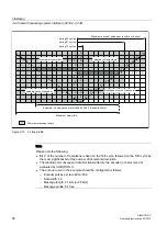
The most significant data bit for the encoder's entire range of values is transmitted by the
encoder with the first cycle.
Subsequent data bits transmitted by the encoder (or zeros) are not evaluated by
SIMOTION C.
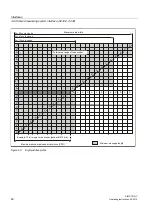
The encoder used in the example should be configured as follows:
– Encoder pulses per revolution: 4096
– Data width: 12
– Message length: 13 bits (or 21 bits or 25 bits)
– Message profile: Right-justified
Encoder supply 5 V
The 5 V supply voltage for the encoders is generated inside the module and is therefore
present at the Sub-D socket. This means you can supply the encoders via the connecting
cable without the need for additional wiring. The voltage supplied is protected electronically
against short circuits and thermal overload, and it is monitored. The encoder supply is not
isolated from the load power supply to the module.
Encoder supply 24 V
For encoders with an operating voltage of 24 V, the 24 VDC power is supplied to the Sub-D
sockets. This means you can supply the encoders via the connecting cable without the need
for additional wiring. The voltage supplied is protected electronically against short circuits
and thermal overload, and it is monitored. The encoder supply is not isolated from the load
power supply to the module.
Behavior of the integrated measurement electronics
Pulses from connected incremental encoders are quadrupled (for pulse quadruplication, see
figure "Signal shapes of incremental encoders").
The actual encoder values are latched servo-synchronously in the C230-2/C240.


