Addressing
6.3 Addressing signal modules
SIMOTION C
138
Operating Instructions, 02/2012
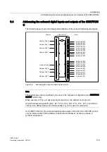
Example for analog modules
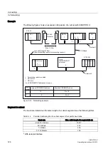
The example in the figure below shows you which default channel addresses are obtained
for an analog module located at slot 4. You will see that in the case of an analog
input/analog output module, the analog input and analog output channels are addressed
from the same address, the module start address.
Slot number 3 is reserved as no interconnection module is present in the example.
6ORW
QXPEHU
60DQDORJPRGXOH
,QSXWV
&KDQQHO$GGUHVV(
&KDQQHO$GGUHVV(
2XWSXWV
&KDQQHO$GGUHVV$
&KDQQHO$GGUHVV$
36
6,027,21&
05(6
6723
581
&
Figure 6-5
Addresses for the inputs and outputs of the analog module in slot 4
Addresses of the FM and CP modules
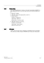
The FM and CP modules are assigned to the analog address range. In addition, the FM and
CP modules have extended interfaces (data sets). For a detailed description, see the
corresponding module's manual.

