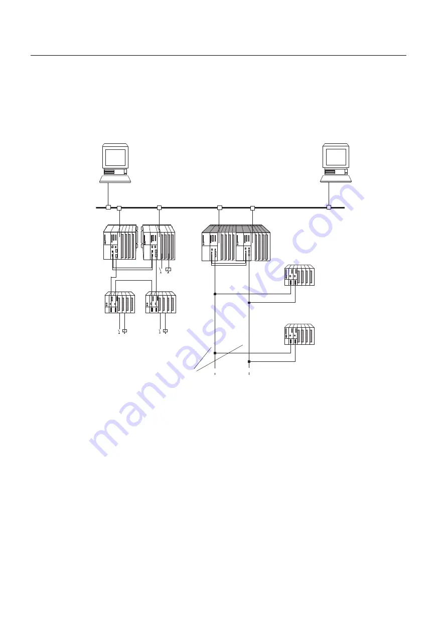
S7-400H setup options
3.1 S7-400H setup options
S7-400H
32
System Manual, 03/2012, A5E00267695-11
The following figure shows an example of an S7-400H configuration with shared distributed
I/O and connection to a redundant plant bus. The next pages deal with the hardware and
software components required for the installation and operation of the S7-400H.
6+DXWRPDWLRQV\VWHP
(70
(70
5HGXQGDQW352),%86'3
(7b0'LVWULEXWHG,2
(7b0'LVWULEXWHG,2
UHGXQGDQWV\VWHPEXV(WKHUQHW
2SHUDWRU6WDWLRQSODQW
YLVXDOL]DWLRQZLWK:LQ&&
5HGXQGDQF\DQG
65('&211(&7
UHGXQGDQWFRPPXQLFDWLRQ
(QJLQHHULQJ6\VWHP
FRQILJXUDWLRQDQGFRQWURO
ZLWK67(3SHUPDQHQWO\
DVVLJQHGWRD&38
Figure 3-1
Overview
Additional information
The components of the S7-400 standard system are also used in the fault-tolerant S7–400H
automation system. For a detailed description of all hardware components for S7–400, refer
to the Reference Manual
S7-400 Automation System; Module Specifications.
The rules governing the design of the user program and the use of function blocks laid down
for the S7-400 standard system also apply to the fault-tolerant S7-400H automation system.
Refer to the descriptions in the
Programming with STEP 7 manual, and to the System
Software for S7-300/400; Standard and System Functions Reference Manual.


