Installation and mounting
5.3 Base area
SICHARGE D
Operating Instructions, 02/2021, 8EM5907-0AA00-1AA7.01
55
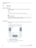
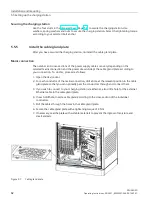
After drilling, insert M12 bolt anchors with suitable fasteners (e.g. dowels). The bolt anchors
must protrude about 50 mm from the foundation.
Figure 5-4
Example of a foundation with bolt anchors and recesses for the various cables
Position the recess for the AC supply cable and DC cable according to the local conditions.
Figure 5-4 shows an example of the AC power supply from the front, while the dispensers are
installed at the side of the charging station. Make the cutouts large enough to make it easy to
lay and connect the cables.
Depending on the installation location, ensure that the foundation depth is sufficient to
guarantee frost-free conditions. Also observe the maximum permissible bending radii of the
connecting cables you are using. Lay communication, control and auxiliary cables separately
and protected from the power cables. To avoid electromagnetic interfaces, a minimum
clearance of 25 cm is recommended. Also avoid routing the cables parallel to the power
cables and, if possible, route the cables orthogonally to the power cables. Observe the
country-specific regulations.
Only use sufficiently insulated cables for the operating voltages. Select the cable cross-
sections according to the rated current, cable length and permissible voltage drop. Also take
into consideration the increased rated current if greater charging power will be desired later.
Fine-stranded or superfine-stranded cables are recommended.
Deep grounding with TT mains
Consider the installation of a deep grounding electrode when connecting the charging
station to a TT mains. The recommended design of the foundation provides sufficient
flexibility for this.

