27/61
Building Technologies
Basic Documentation LMO39…
CC1P7154en
9 Operation, indication, diagnostics
15.03.2018
9.3 Diagnostics of cause of fault
:
After a non-alterable lockout, the red signal lamp is steady on. In that condition, visual
diagnostics of the cause of fault according to the error code table can be activated by
pressing the lockout reset button for more than 3 seconds. Pressing the lockout reset
button again for at least 3 seconds activates interface diagnostics. Interface diagnostics
works only if the AGK20... lockout reset button extension is not fitted. If, by accident,
interface diagnostics has been activated, in which case the slightly red light of the
signal lamp flickers, it can be deactivated by pressing again the lockout reset button for
at least 3 seconds. The moment of switching over is indicated by a yellow light pulse.
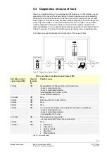
The following sequence activates the diagnostics of the cause of fault:
EK
> 3 s
EK
> 3 s
Interface diagnostics
PC / analyzer
EK
< 3 s
71
06
z0
4e
/1
01
1
Reset
On
Visual diagnostics
Lockout position
Lockout position
Lockout position
Figure 7: Diagnostics of cause of fault
Error code table of multicolor signal lamp (LED)
Red blink code of
signal lamp (LED)
Alarm at
terminal
10
Possible cause
2 blinks
ON
No establishment of flame at the end of safety time
- faulty or soiled fuel valves
- faulty or soiled flame detector
- poor adjustment of burner, no fuel
- faulty ignition equipment
3 x blinks
ON
Free
4 blinks
ON
Extraneous light on burner startup
5 blinks
ON
Free
6 blinks
ON
Free
7 blinks
ON
Too many losses of flame during operation (limitation of repetitions)
- faulty or soiled fuel valves
- faulty or soiled flame detector
- poor adjustment of burner
8 x blinks
ON
Time supervision oil preheater
- oil preheater failed 5 times during prepurging
9 blinks
ON
Free
10 blinks
OFF
∂
Wiring
error
∂
Internal
error
∂
Output
contacts
∂
Other
fault
∂
Manual
lockout
Table 7: Error code table


