20/61
Building Technologies
Basic Documentation LMO39…
CC1P7154en
6 Technical data
15.03.2018
6 Technical data
6.1 General unit data
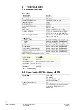
Mains voltage
- LMO39.100x1
- LMO39.100x2
AC 120 V
AC 230 V
Mains frequency
50...60 Hz
External primary fuse (Si)
T6.3H250V to IEC 60127-2
Power consumption
12 VA
Mounting position
Optional
Input current at terminal 1
Max. 5 A
Weight
Approx. 160 g
Safety class
I
(burner control with plug-in base)
Degree of protection
IP40 (to be ensured through mounting)
(if RJ11 jack is not covered, only IP10)
Perm. cable length terminal 1
Max. 1 m at a line capacitance of 100 pF/m
(max. 3 m at 15 pF/m)
Cable lengths
∂
QRB1 / QRB3
Max. 10 m at 100 pF/m (laid separately)
∂
QRB4
Max. 3 m at 100 pF/m (laid separately)
∂
QRC
Max. 10 m at 100 pF/m (laid separately)
Remote reset
Max. 20 m at 100 pF/m (
laid separately
)
Detector cable
Max. 10 m at 100 pF/m (
laid separately
)
Control thermostat/pressurestat
Max. 20 m at 100 pF/m (
laid separately
)
Limit thermostat/pressure switch
Max. 20 m at 100 pF/m (
laid separately
)
Alarm terminal 10
Max. 20 m at 100 pF/m (
laid separately
)
Possible input current terminals 7 and 9
1 mA
Current rating
At cos
ι ″
0.6
- Terminal 1
Max. 5 A
- Terminals 3 and 8
Max 3 A (15 A during max. 0.5 s)
- Terminals 4, 5 and 10
Max. 1 A
- Terminal 6
Max. 2 A
Table 2: Perm. terminal rating
6.2 Signal cable AGV50... display
↑
BCI
Signal cable
Color white
Unshielded
Conductor 4 x 0.141 mm²
with RJ11-connector
Cable length AGV50.100
1 m
Location
Under the burner hood (extra measures
required for compliance with SKII
EN 60730-1)

