ECO REFERENCE MANUAL
13-11
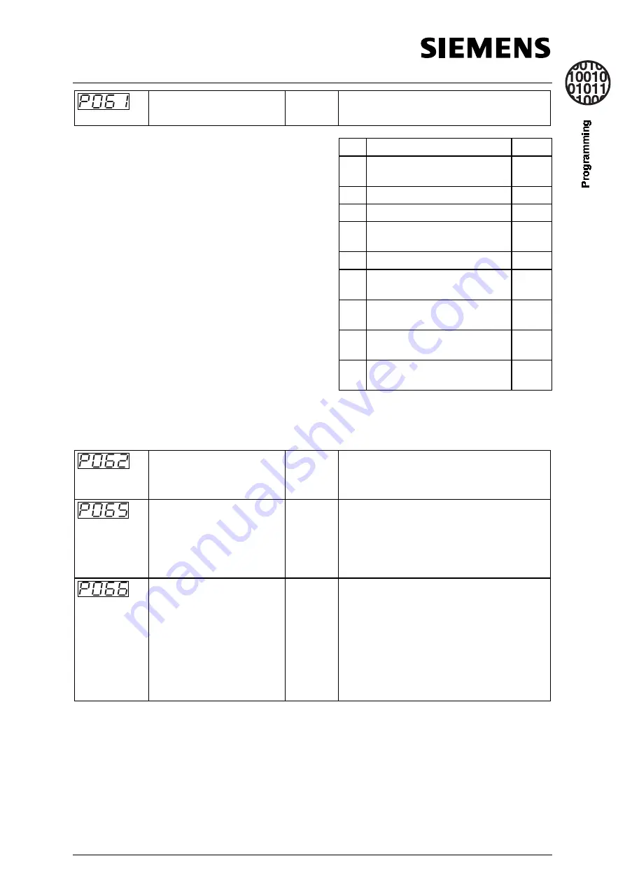
Selection relay output RL1
0 - 13
[6]
Sets the relay function, output RL1
(terminals 18,19 and 20)
Value
Relay function
Active
3
0
No function assigned (relay not
active)
Low
1
Inverter is running
High
2
Inverter frequency 0.0 Hz
Low
5
Inverter frequency less than or equal
to minimum frequency
Low
6
Fault indication
1
Low
7
Inverter frequency greater than or
equal to setpoint
High
9
Output current greater than or equal
to P065
High
12
PID closed loop motor LOW speed
limit
High
13
PID closed loop motor HIGH speed
limit
High
1
Inverter switches off (see parameter P930 and P140 to P143 and section 7).
2
Inverter does not trip(see parameter P931).
3
‘Active low’ = relay OFF/ de-energised or ‘Active high’ = relay ON/ energised
Selection relay output RL2.
Models above 7.5kW only
0 - 13
[1]
Sets the relay function, output RL2
(terminals 21and 22)
(refer to the table in
P061)
.
Current threshold for relay
(A)
0.0-300.0
[1.0]
This parameter is used when P061 = 9. The
relay switches on when the motor current is
greater than the value of P065 and switches
off when the current falls to 90% of the value
of P065 (hysteresis).
Compound braking
0 - 250
[0]
0 = Off
1 to 250 = Defines the level of DC
superimposed on the AC waveform,
expressed as a percentage of P083.
Generally, increasing this value improves
braking performance, however, with 400V
inverters, a high value in this parameter
could cause F001 trips.


