
7SR210 & 7SR220 Description of Operation
Unrestricted Page 66 of 94
©2018 Siemens Protection Devices Limited
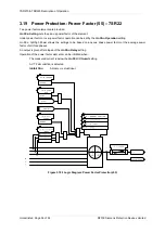
4.9
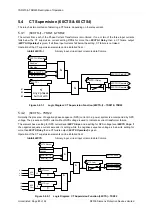
Synchronising
The optional Synchronising function is used to check that the voltage conditions, measured by the voltage
transformers on either side of the open circuit breaker, indicate that it is safe to close without risk of damage to
the circuit breaker of disturbance to the system. The timing of closure, for charging lines which are dead following
fault clearance, is controlled to co-ordinate with other devices.
The window of time in which voltage conditions must be met is applied as a setting or can be disabled such that
an indefinite period is allowed.
4.9.1
Reclosure Modes
The Synchronising element can be set to allow the autoreclose sequence to proceed for various system voltage
conditions. The voltage conditions selected must be met within the
Synch Close Window
time if this is Enabled,
this time can be set and starts at the end of the deadtime for autoreclose or the receipt of a Close CB command.
The voltage applied to the V
4
input is considered to be the BUSBAR voltage and the voltages applied to inputs
V
1
,V
2
& V
3
are the LINE voltage.
79 Dead Bar Charge
, when set to Enabled, allows AR to proceed when the Line voltage is live and the Busbar is
dead.
Manual Close DBC
, when set to Enabled, allows MC to proceed when the Line voltage is live and the Busbar is
dead.
79 Dead Line Charge
, when set to Enabled, allows AR to proceed when the Busbar voltage is live and the Line is
dead.
Manual Close DLC
, when set to Enabled, allows MC to proceed when the Busbar voltage is live and the Line is
dead.
79 Dead Line & Dead Bar Close
, when set to Enabled, allows AR to proceed when the Line voltage and the
Busbar voltage are dead.
Manual Close DLDB
, when set to Enabled, allows MC to proceed when the Line voltage and the Busbar voltage
are dead.
79 Check Sync Close
, when set to Enabled, allows AR to proceed when both the Line and Busbar are
considered live AND other synchronising requirements are met.
Manual Close CS
, when set to Enabled, allows MC to proceed when both the Line and Busbar are considered
live AND other synchronising requirements are met.
79 Unconditional Close
, when set to Enabled, allows AR to proceed regardless of the voltage condition of the
Bus or Line.
Unconditional Manual Close
, when set to Enabled, allows MC to proceed regardless of the voltage condition of
the Bus or Line.
Separate Enable/Disable settings are thus provided for each option for Autoreclose and Manual Close.
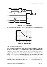
4.9.2
Charge Delays
Separate autoreclose delay settings are provided for Dead Line Charge and Dead Bus Charge closure by the
79
DLC Delay
and
79 DBC Delay
settings. These are applied after the autoreclose Dead Time when voltage
conditions are checked and met, at the Close Inhibit stage of the sequence. This feature effectively allows the
dead time to be set differently for faults on each side of the recloser.
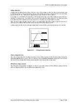
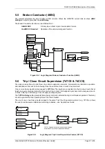
4.9.3
Voltage monitoring elements
The single phase voltage source used for synchronising can be selected as any phase-to-phase or phase-to-earth
voltage for flexibility. The voltage is compared to the corresponding voltage from the three-phase arrangement on
the other side of the circuit-breaker. Voltage settings are set as a percentage of the nominal voltage specified in
the CT/VT Config menu.
Summary of Contents for Argus 7SR21
Page 1: ...Energy Management 7SR21 7SR22 Argus Overcurrent Relay Reyrolle Protection Devices ...
Page 2: ......
Page 4: ...Contents 7SR11 and 7SR12 Page 2 of 2 2018 Siemens Protection Devices Limited ...
Page 185: ...7SR210 Settings Guide Unrestricted 2018 Siemens Protection Devices Limited Page 61 of 61 ...
Page 277: ...7SR220 Settings Guide Unrestricted Page 72 of 107 2013 Siemens Protection Devices Limited ...
Page 382: ...7SR220 Technical Manual Chapter 4 Page 2 of 96 2017 Siemens Protection Devices Limited ...
Page 386: ...7SR220 Technical Manual Chapter 4 Page 6 of 96 2017 Siemens Protection Devices Limited ...
Page 398: ...7SR220 Technical Manual Chapter 4 Page 18 of 96 2017 Siemens Protection Devices Limited ...
Page 414: ...7SR220 Technical Manual Chapter 4 Page 34 of 96 2017 Siemens Protection Devices Limited ...
Page 466: ...7SR220 Technical Manual Chapter 4 Page 86 of 96 2017 Siemens Protection Devices Limited ...
Page 468: ...7SR220 Technical Manual Chapter 4 Page 88 of 96 2017 Siemens Protection Devices Limited ...
Page 470: ...7SR220 Technical Manual Chapter 4 Page 90 of 96 2017 Siemens Protection Devices Limited ...
Page 472: ...7SR220 Technical Manual Chapter 4 Page 92 of 96 2017 Siemens Protection Devices Limited ...
Page 643: ...Unrestricted ...