7SR210 & 7SR220 Applications Guide
Page 26 of 48
©2018 Siemens Protection Devices Limited
2.13 Under/Over Voltage Protection (27/59)
Power system under-voltages on may occur due to:
System faults.
An increase in system loading,
Non-energized power system e.g. loss of an incoming transformer
During normal system operating conditions regulating equipment such as transformer On Load Tap Changers
(OLTC) and generator Automatic Voltage Regulators (AVR) ensure that the system runs within acceptable
voltage limits.
7SR24 undervoltage/DTL elements can be used to detect abnormal undervoltage conditions due to system
overloads. Binary outputs can be used to trip non-essential loads - returning the system back to its normal
operating levels. This ‘load shedding’ should be initiated via time delay elements so avoiding operation during
transient disturbances. An under voltage scheme (or a combined under frequency/under voltage scheme) can
provide faster tripping of non-essential loads than under-frequency load shedding so minimising the possibility of
system instability.
Where a transformer is supplying 3-phase motors a significant voltage drop e.g. to below 80% may cause the
motors to stall. An undervoltage element can be set to trip motor circuits when the voltage falls below a preset
value so that on restoration of supply an overload is not caused by the simultaneous starting of all the motors. A
time delay is required to ensure voltage dips due to remote system faults do not result in an unnecessary
disconnection of motors.
To confirm presence/loss of supply, the voltage elements should be set to values safely above/below that where a
normal system voltage excursion can be expected. The switchgear/plant design should be considered. The ‘Dead’
level may be very near to the ‘live’ level or may be significantly below it. The variable hysteresis setting allows the
relay to be used with all types of switchgear.
System over-voltages can damage component insulation. Excessive voltage may occur for: -
Sudden loss of load
A tap changer run-away condition occurs in the high voltage direction,
Generator AVR equipment malfunctions or
Reactive compensation control malfunctions.
System regulating equipment such as transformer tap changers and generator AVRs may correct the overvoltage
– unless this equipment mal-functions. The overvoltage/DTL elements can be used to protect against damage
caused by system overvoltages.
If the overvoltage condition is small a relatively long DTL time delay can be used. If the overvoltage is more
severe then another element, set at a higher pickup level and with a shorter DTL can be used to isolate the circuit
more quickly. Alternatively, elements can be set to provide alarm and tripping stages, with the alarm levels set
lower than the tripping stages.
The use of DTL settings allows a grading system to be applied to co-ordinate the network design, the regulating
plant design, system plant insulation withstand and with other overvoltage relays elsewhere on the system. The
DTL also prevents operation during transient disturbances.
The use of IDMTL protection is not recommended because of the difficulty of choosing settings to ensure correct
co-ordination and security of supply.
Summary of Contents for Argus 7SR21
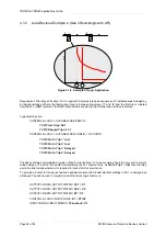
Page 1: ...Energy Management 7SR21 7SR22 Argus Overcurrent Relay Reyrolle Protection Devices ...
Page 2: ......
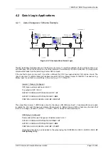
Page 4: ...Contents 7SR11 and 7SR12 Page 2 of 2 2018 Siemens Protection Devices Limited ...
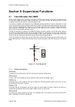
Page 185: ...7SR210 Settings Guide Unrestricted 2018 Siemens Protection Devices Limited Page 61 of 61 ...
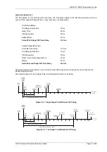
Page 277: ...7SR220 Settings Guide Unrestricted Page 72 of 107 2013 Siemens Protection Devices Limited ...
Page 382: ...7SR220 Technical Manual Chapter 4 Page 2 of 96 2017 Siemens Protection Devices Limited ...
Page 386: ...7SR220 Technical Manual Chapter 4 Page 6 of 96 2017 Siemens Protection Devices Limited ...
Page 398: ...7SR220 Technical Manual Chapter 4 Page 18 of 96 2017 Siemens Protection Devices Limited ...
Page 414: ...7SR220 Technical Manual Chapter 4 Page 34 of 96 2017 Siemens Protection Devices Limited ...
Page 466: ...7SR220 Technical Manual Chapter 4 Page 86 of 96 2017 Siemens Protection Devices Limited ...
Page 468: ...7SR220 Technical Manual Chapter 4 Page 88 of 96 2017 Siemens Protection Devices Limited ...
Page 470: ...7SR220 Technical Manual Chapter 4 Page 90 of 96 2017 Siemens Protection Devices Limited ...
Page 472: ...7SR220 Technical Manual Chapter 4 Page 92 of 96 2017 Siemens Protection Devices Limited ...
Page 643: ...Unrestricted ...

