


Chapter 4 - Data Communications Definitions
© 2017 Siemens Protection Devices Limited
Chapter 4 - Page 83 of 96
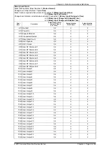
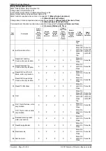
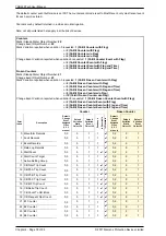
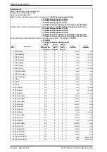
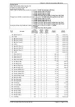
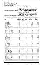
Analog Inputs
Static (Steady-State) Object Number:
30
Change Event Object Number:
32
Analog Input Deadband:
34
Static Variation reported when variation 0 requested:
1 (32-Bit Analog Input with Flag)
or
2 (16-Bit Analog Input with Flag)
or
3 (32-Bit Analog Input w/o Flag)
or
4 (16-Bit Analog Input w/o Flag)
or
5 (Single Precision, floating point Analog Input with Flag)
Change Event Variation reported when variation 0 requested:
1 (32-Bit Analog Change Event w/o Time)
or
2 (16-Bit Analog Input w/o Time)
or
3 (32-Bit Analog Input with Time)
or
4 (16-Bit Analog Input with Time)
or
5 (Single Precision, floating point Analog Input w/o Time)
or
7 (Single Precision, floating point Analog Input with Time)
Analog Input Reporting Deadband Variation reported when variation 0 requested:
1 (16-Bit)
or
2 (32-Bit)
or
3 (Single Precision, floating point)
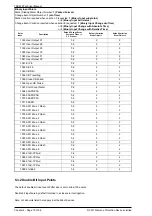
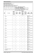
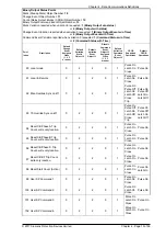
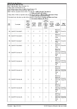
Point
Description
Index
185 CB Wear B
Default
Change Event
Assigned Class
(1, 2, 3 or none)
0,3
Default
Variation
Static
Object 30
1
Default
Variation
Event
Object 32
3
Default
Multiplier
0.000
Default
Deadband
1000000.000
186 CB Wear C
0,3
1
3
0.000
1000000.000
187 CB Wear A Remaining
0,3
1
3
1.000
1.000
188 CB Wear B Remaining
0,3
1
3
1.000
1.000
189 CB Wear C Remaining
0,3
1
3
1.000
1.000
190 CB Wear Minimum
0,3
1
3
1.000
1.000
191 Fault Distance Perunit
0,3
5
7
0.001
1.000
196 Frequency Max
0,3
2
4
100.000
1.000
197 S 3P Max
0,3
2
4
0.000
1000000.000
318 Sec Active Power A
0,3
2
4
1.000
10.000
319 Sec Active Power B
0,3
2
4
1.000
10.000
320 Sec Active Power C
0,3
2
4
1.000
10.000
321 Sec P (3P)
0,3
2
4
1.000
10.000
322 Sec Reactive Power A
0,3
2
4
1.000
10.000
323 Sec Reactive Power B
0,3
2
4
1.000
10.000
324 Sec Reactive Power C
0,3
2
4
1.000
10.000
325 Sec Q (3P)
0,3
2
4
1.000
10.000
326 Sec Apparent Power A
0,3
2
4
1.000
10.000
327 Sec Apparent Power B
0,3
2
4
1.000
10.000
328 Sec Apparent Power C
0,3
2
4
1.000
10.000
329 Sec S (3P)
0,3
2
4
1.000
10.000
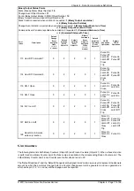
330 CB Trip Time Meter
0,3
2
4
1000.000
0.010
337 PF 3P Max
0,3
2
4
1000.000
0.100
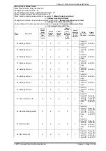
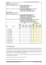
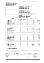
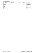
5.4 Additional Settings
The following relay settings are provided for configuration of the DNP 3.0 implementation when available and are
common to all ports using this protocol.
Setting Name
Range/Options
Default
Setting
Notes
Unsolicited
Mode
DISABLED, ENABLED
DISABLED
As Required
Setting is only visible
when any port
Protocol is set to
DNP3.
Summary of Contents for Argus 7SR21
Page 1: ...Energy Management 7SR21 7SR22 Argus Overcurrent Relay Reyrolle Protection Devices ...
Page 2: ......
Page 4: ...Contents 7SR11 and 7SR12 Page 2 of 2 2018 Siemens Protection Devices Limited ...
Page 185: ...7SR210 Settings Guide Unrestricted 2018 Siemens Protection Devices Limited Page 61 of 61 ...
Page 277: ...7SR220 Settings Guide Unrestricted Page 72 of 107 2013 Siemens Protection Devices Limited ...
Page 382: ...7SR220 Technical Manual Chapter 4 Page 2 of 96 2017 Siemens Protection Devices Limited ...
Page 386: ...7SR220 Technical Manual Chapter 4 Page 6 of 96 2017 Siemens Protection Devices Limited ...
Page 398: ...7SR220 Technical Manual Chapter 4 Page 18 of 96 2017 Siemens Protection Devices Limited ...
Page 414: ...7SR220 Technical Manual Chapter 4 Page 34 of 96 2017 Siemens Protection Devices Limited ...
Page 466: ...7SR220 Technical Manual Chapter 4 Page 86 of 96 2017 Siemens Protection Devices Limited ...
Page 468: ...7SR220 Technical Manual Chapter 4 Page 88 of 96 2017 Siemens Protection Devices Limited ...
Page 470: ...7SR220 Technical Manual Chapter 4 Page 90 of 96 2017 Siemens Protection Devices Limited ...
Page 472: ...7SR220 Technical Manual Chapter 4 Page 92 of 96 2017 Siemens Protection Devices Limited ...
Page 643: ...Unrestricted ...