7SG12 DAD N Applications Guide
Contents
Figures
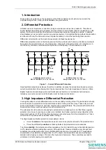
Figure 1 – Current Differential Protection................................................................................................................. 3
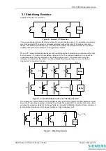
Figure 2 – Simple 4 CT Protection ........................................................................................................................... 4
Figure 3 – Current Distribution with one CT totally saturated................................................................................... 4
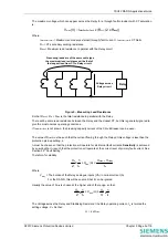
Figure 4 – Stabilising Resistor ................................................................................................................................. 4
Figure 5 – Measuring Lead Resistance ................................................................................................................... 5
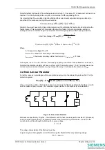
Figure 6 – Non-Linear Resistor ................................................................................................................................ 6
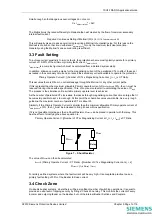
Figure 7 – Shunt Resistor ........................................................................................................................................ 7
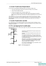
Figure 8 – Check Zone Relay .................................................................................................................................. 8
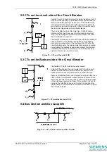
Figure 9 – CTs Overlapping the CB ......................................................................................................................... 9
Figure 10 – CTs on other side of CB...................................................................................................................... 10
Figure 11 – CTs on Busbar side of CB .................................................................................................................. 10
Figure 12 – CTs on Bus Section and Bus Coupler................................................................................................. 10
Figure 13 – DAD-N Connection Diagram............................................................................................................... 12
Figure 14 – Typical High Impedance Protection Components ............................................................................... 13
Figure 15 – High Impedance Protection of Auto-transformer................................................................................. 14
Figure 16 – High Impedance Protection of Motor, Generator or Reactors ............................................................. 15
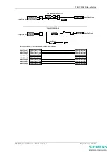
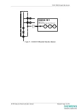
Figure 17 – DAD-N-101 Differential Protection Elements ...................................................................................... 16
©2010 Siemens Protection Devices Limited
Chapter 5 Page 2 of 16
Summary of Contents for 7SG12 DAD-N
Page 2: ......

