7SG12 DAD N Applications Guide
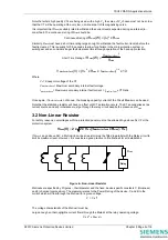
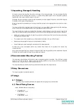
The maximum voltage which can appear across the Relay for a through fault coincident with CT saturation
is:
))
R
x
(2
(R
x
I
(V)
V
lead
ct
ault
MaxSecExtF
max
+
=
Where:
I
MaxSecExtFault
= Maximum secondary external (through) fault current = I
MaxPriExtFaul
x CT Ratio
R
ct
= CT secondary winding resistance
R
lead
= Maximum lead resistance in parallel with the Relay circuit
Relay
Presuming leads are of the same cable type
the maximum lead resistance will be that of
the longest lead from CT to Relay circuit
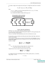
Voltage across
Relay circuit
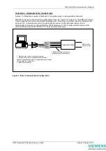
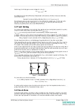
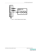
Figure 5 – Measuring Lead Resistance
So that R
lead
+ R
ct
+ R
lead
is the total resistance in parallel with the Relay.
There will be some lead resistance between the Relay and the closest CT, but this is generally ignored to
give the most onerous operating conditions.
If I
MaxPriExtFault
is not known, the breaking capacity current of the Circuit Breaker can be used.
The value of R
stab
must be such that the current flowing through the Relay at this voltage is less than the
protection pick-up setting, I
s
.
I
s
must be chosen so that the protection will operate for all internal fault currents.
Sensitivity
is achieved
by ensuring that I
s
is such that the protection will operate at the correct level of primary fault current. See
Section 3.3 “Fault Setting”.
Therefore, for stability:
s
k
I
1
x
2
V
≥
R
stab
(
Ω
)
s
relay
max
I
V
-
V
≥
Where:
V
relay
= The burden of the Relay analogue inputs (VA) / nominal current (A)
For the DAD-N, this will be so small that it can be ignored
Usually the value of R
stab
is chosen at the higher end of the range, so that:
s
k
I
1
x
2
V
≥
R
stab
(
Ω
)
≥
s
k
I
1
x
4
V
The Voltage across the Relay and Stabilising Resistor at the Relay operating current, I
s
, is termed the
setting voltage, V
s
. So that:
V
s
= I
s
x R
stab
©2010 Siemens Protection Devices Limited
Chapter 5 Page 5 of 16
Summary of Contents for 7SG12 DAD-N
Page 2: ......

