7SG12 DAD N Description of Operation
be made without re-entering the password. If no more changes are made within 1 hour then the user will
automatically be ‘logged off’, re-enabling the password feature.
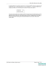
Note that the password validation screen also displays a numerical code. If the password is lost or
forgotten, this code should be communicated to VA TECH Reyrolle ACP Ltd and the password can be
retrieved.
5 User Interface
The user interface is designed to provide a user-friendly method of entering settings and retrieving data
from the relay. The E8 relay fascia includes a 20 character by 2 line, backlit, liquid crystal display (LCD), 16
light emitting diodes (LED) and 5 push buttons.
5.1 Liquid Crystal Display
The liquid crystal display is used to present settings, instrumentation and fault data in a textual format on a
2 lines by 20-character interface.
5.2 Back Light Control
To conserve power the display backlighting is turned off if no push buttons are pressed for 5 minutes.
After an hour the whole display is de-activated. A setting within the “SYSTEM CONFIG MENU” allows the
timeout to be adjusted from 1 to 60 minutes and “OFF”, which means the backlight is always on.
5.3 LED Indications
The following indications are provided:
Protection Healthy – Green LED.
This LED is solidly illuminated to indicate that DC volts have been applied to the relay and that the relay is
operating correctly. If the internal relay watchdog detects a protection relay unhealthy condition then this
LED will continuously flash.
Programmable – Red LED.
An LED MENU is provided to map any relay output or any status input to any LED.
5.4 Keypad
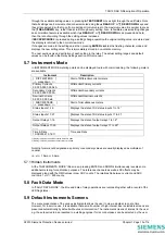
Five pushbuttons are used to control the functions of the relay. They are labelled
ENTER
and
CANCEL
.
Note that the
►
button is also labelled
TEST/RESET
.
When the relay front cover is in place only the
▼
and
►
buttons are accessible. This allows read only
access to all the menu displays.
5.5 Relay Identifier
The Relay Identifier setting in the SYSTEM CONFIG MENU may be used to place a circuit identifier of up
to 16 alphanumeric characters onto the relay fascia. This information is also returned as part of the System
Information command from Reydisp Evolution Communications Support Software.
5.6 Settings Mode
5.6.1 Settings Adjustment
The push-buttons on the fascia are used to display the relay settings, display the operating signals, e.g.
currents, on the LCD and to reset the flag indication on the LCDs.
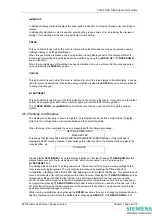
▼
READ DOWN
In the Settings Display this push-button is used for scrolling down through a list of settings or signals.
In Settings Modification mode it is used for selecting the next value of (or decreasing) the displayed setting
or for deselecting a bit position in a particular control setting.
©2010 Siemens Protection Devices Limited
Chapter 1 Page 8 of 14
Summary of Contents for 7SG12 DAD-N
Page 2: ......

