7SG12 DAD N Commissioning
To download a Settings File on the laptop, select Relay->Settings->Send All Settings. Confirm the action and the
program will inform whether the settings have been successfully entered into the relay. It is worth doing a few spot
checks on the settings to be confidant the correct settings are installed.
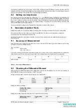
8.2 Setting via relay fascia
The relay can be set from the fascia by utilising the
×
,
Ø
,
Ö
and ENTER buttons. Settings can be selected with
the arrow buttons. Pressing ENTER when the setting to change is found will make the setting flash. This allows
the
×
and
Ø
buttons to be used to alter the setting. Once the desired setting is selected the ENTER pushbutton
MUST be pressed for the relay to active the selected setting. The setting will now stop flashing indicating this
value will be utilised by the relay software.
The menu structure is shown in the “Description of Operation“ section of this manual.
9. Secondary Injection Tests
Isolate the auxiliary D.C. supplies for alarm and tripping from the relay and remove the trip and intertrip links.
We recommend the use of an Omicron Test Set Type CMA156. The Omicron set should be connected in
accordance with the manufacturer’s instructions.
By default all protection elements are disabled, however if this is not the case, then disable all protection and
alarm elements.
9.1 Accuracy of Measurement
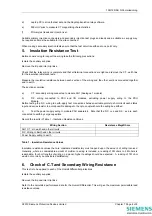
Inject all of the current inputs with nominal current in turn, and record the following currents measured by the relay
in Table 3 – Accuracy of Measurement.
Tap
Ø
to select: -
e.g.
Diff
Currents
0.00 0.00 0.00 x I
n
If the relay measurement is within tolerance proceed to 9.2 below. If any of the measurements are outside the
stated tolerance (±5%) the relay must be sent back to the Quality Assurance Department for investigation.
Meter
A B C
Diff1 Currents
A xIn
B xIn
C xIn
Table 3 – Accuracy of Measurement
9.2 Checking the Differential Element
When testing the Differential Element the Differential Currents can be displayed on the LCD by changing to
INSTRUMENTS mode and scrolling down to [Diff1 Currents].
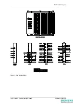
Connect a single phase current source to Phase A, see Table below :-
Connection
Phase Unit
Start
Finish
A AN1C1
17 18
B AN1C2
21 22
C AN1C3
25 26
Modify the following settings :-
Setting Description
Setting Value
87/50 Element
Enable
87/50 Delay
0.1
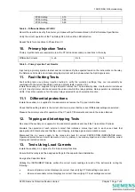
Modify the operate setting and determine the PU and DO at each setting :-
Setting Description
Setting Value
PU
DO
87/50 Setting
0.05
©2010 Siemens Protection Devices Limited
Chapter 7 Page 6 of 8
Summary of Contents for 7SG12 DAD-N
Page 2: ......


