H39.MFVRS004EN-00
02.2019
41/64
Assembly instructions
Multi-point locks, key operated
BS 230X, BS 250X, BS 260X
4.10.3
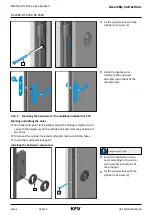
Mounting the hardware for the safety lock T2
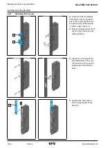
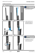
Marking and drilling the holes
f
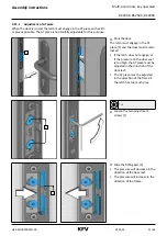
With the multi-point lock installed, adjust the drilling template (enclo-
sed with the hardware) on the square spindle and mark the positions of
the holes.
f
Dismount the multi-point lock and drill the holes.
f
Install the multi-point lock again.
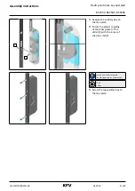
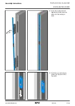
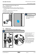
Installing the hardware components
1
Fixing screw [1] = M4
f
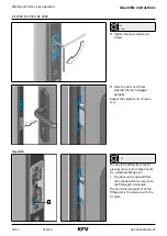
Install the hardware compo-
nents according to the enclo-
sed assembly instructions of
the producer.
4.11
Milling the frame
4.11.1
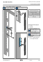
Assembly specifications for SKG certified frame parts
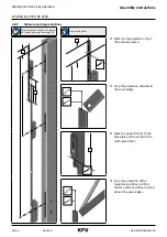
The dimensions for the vertical position must be exactly adhered to for the assembly of the
frame parts. Consequently, it is ensured that the hook bolt can move fully into the locking
position and achieve the specified minimum dimension for the grip into the frame part.
9,5
0
8,5
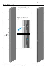
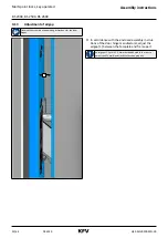
The hook bolt must lock min. 9.5
mm into the frame part.
The hook bolt must move smoo-
thly and completely into the
locking position and the release
position.
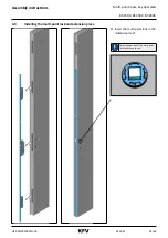
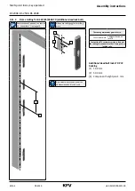
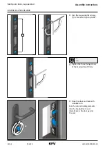
Position the required routed po-
ckets and mount the frame parts
with the specified screws, (see
chapter 4.12 „Screwing specifi-
cations for SKG certified frame
9,5
0
8,5


