


33
8015383/ZUQ7/V1-3/2020-06 | SICK
O P E R A T I N G I N S T R U C T I O N S | TRANSIC151LP
Subject to change without notice
OPERATION
4
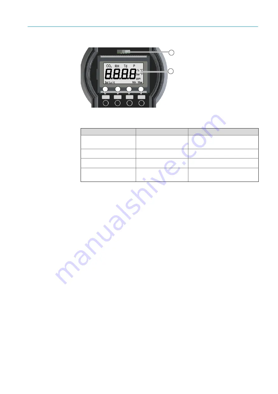
Fig. 14: Display and keypad
Display modes
The display is in one of the following modes when no input is made:
4.2.2
Maintenance interface
The maintenance interface is located on the connector block above the display. It serves:
– Maintenance
– Calibration
– Changing parameters.
All adjustable parameters can be accessed with a PC terminal program (e.g.,
Hyperterminal) via the serial maintenance interface.
A special interface cable serves to connect the TRANSIC151LP and the PC.
The maintenance interface provides more configuration options for alarm threshold(s) or
other settings than the keypad and display.
4.2.3
Analog output
The TRANSIC151LP has a non-insulated current output. The configuration of the active
analog output (0 or 4 ... 20 mA) and the switching behavior in an error state are determined
at order time. These parameters can be changed via the maintenance interface.
4.2.4
NAMUR digital output
The NAMUR digital output can be configured at order time so that it signals limit value
overflows or underflows, warnings or device errors. These settings can be changed via the
maintenance interface.
Up
DN
Back
Ent
1 LED (red/yellow/green)
2 Seven-part display
3
Up
- Upwards button
4
Dn
- Downwards button
5
Back
- Back button
6
Ent
- Input button
4
5
6
1
2
3
Display modes
Display / LED
Process
Start
(duration: 2.5 minutes)
Software version
Self-test
PASS
Self-test starts
Information: Self-test running
Warming up phase starts.
Normal operation
Green LED remains on
Measured oxygen value
Measured oxygen value is shown
continuously.
Error state
Red LED remains on
Error state number
Warning
Yellow LED blinks
Measured oxygen value is
displayed
Select function
Err
in the menu or
Error Table,
.
Table 1: Display modes