6.10
Wiring the CAN interface
NOTE
Activate the CAN data interface in the device with a configuration tool, e.g. the configu‐
ration software SOPAS ET.
Make further settings in the device corresponding to the function of the device in the
system configuration.
Wiring the CAN interface of the device via a connection module:
Connection mod‐
ule
Interface
Reference
CDB650-204
CAN
see "Wiring the CAN interface in the CDB650-204",
page 107
CDM420-0006
CAN
see "Wiring the CAN interface in the CDM420-0006",
page 120
6.11
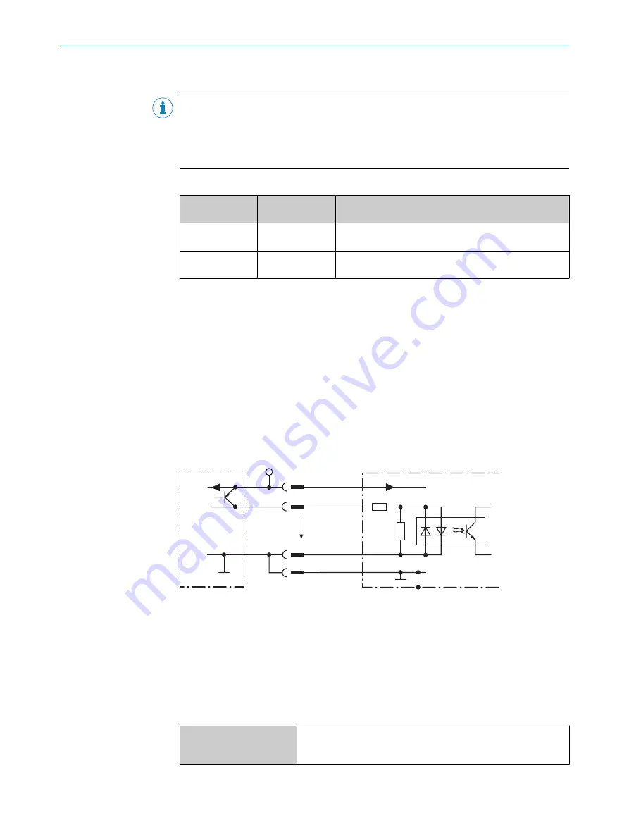
Wiring the digital switching inputs
Physical switching inputs on the device
The two physical digital switching inputs “Sensor 1” and “Sensor 2” can, for example,
be used for starting and/or ending the read cycle, or for feeding an incremental signal.
The full complement of digital switching inputs is available in each case:
•
at the male connector of the device (M12, 17-pin, A-coded)
•
at the adapter cable (female connector, M12, 17-pin, A-coded/male connector, D-
Sub-HD, 15-pin)
•
at the open end of the adapter cable (female connector, M12, 17-pin, A-coded /
open end)
Signal
3
3.32K
6.64K
"
§
$
Sensor GND
V
S
2
V
S
V
S
V
in
5
!
PNP sensor
1
GND
GND
Switching input of device
4
GND
V
S
Figure 37: Wiring a digital switching input
1
Trigger sensor (PNP sensor)
2
Supply voltage V
S
(V
S
= U
V
)
3
Input signal
4
Switching input of the device (“Sensor 1” or “Sensor 2”)
5
Input voltage V
in
(V
in
= U
e
)
!
...
$
For pin assignment, see respective device
Table 15: Characteristic data of the digital switching inputs “Sensor 1” and “Sensor 2”
Switching behavior
Power to the input starts the assigned function, e.g. start of the
internal reading interval of the device Default: active high,
debounce time: 10 ms (standard)
ELECTRICAL INSTALLATION
6
8014335/ZTL9/2018-10-14 | SICK
O P E R A T I N G I N S T R U C T I O N S | RFU63x, RFU65x
67
Subject to change without notice


