6.5.10
Evaluation mode
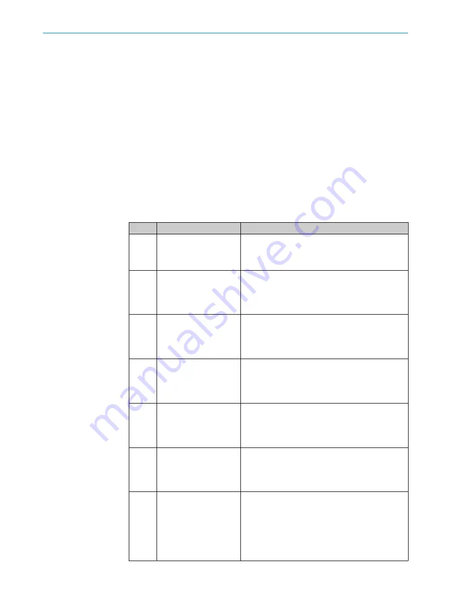
The configured evaluation mode affects which circle is detected as the positioning mark
and used for the output of measured values. The following table provides information
on the available evaluation modes.
In evaluation modes 1 to 8, the user defines a target region in which the positioning
mark is located.
In evaluation modes 9 to 14, the user defines an area that will be excluded from
the evaluation. Only circles within the target region will be used for the evaluation.
The device ignores all circles outside the target region. The digital outputs are not
supported in evaluation modes 9 to 14.
The device determines the location of the positioning mark based on a coordinate
system in the field of view. The measured value (X value and Y value) that the device
outputs is relative to the origin of the coordinate system. When evaluation mode 1 to 8
is set, the origin is located in the middle of the target region. For evaluation modes 1 to
8, the origin can also be shifted in SOPASair using the
Relative offset to origin X [mm]
and
Relative offset to origin Y [mm]
parameters. When evaluation mode 9 to 14 is set, the origin
is located at the center point of the image.
No.
Evaluation mode
Description
1
Best circle score
The circle with the highest measured score value
1)
is
used for the output of measured values. To exclude
circles with a too low measured score value from the
evaluation, adjust the
Min acceptance score
parameter.
2
First circle left
The circle with the smallest distance from the left edge
of the image is used for the output of measured values.
This is the circle with the smallest value for the
Auto‐
mated storage and retrieval system relative position correction X
parameter.
3
First circle right
The circle with the smallest distance from the right edge
of the image is used for the output of measured val‐
ues. This is the circle with the largest value for the
Auto‐
mated storage and retrieval system relative position correction X
parameter.
4
First circle top
The circle with the smallest distance from the top edge
of the image is used for the output of measured values.
This is the circle with the smallest value for the
Auto‐
mated storage and retrieval system relative position correction Y
parameter.
5
First circle bottom
The circle with the smallest distance from the bottom
edge of the image is used for the output of measured
values. This is the circle with the largest value for the
Automated storage and retrieval system relative position correc‐
tion Y
parameter.
6
Circle nearest to the origin
The circle with the smallest distance from the origin is
used for the output of measured values. The origin is
located in the center of the image. The origin can also be
shifted using the
Relative offset to origin X [mm]
and
Relative
offset to origin Y [mm]
parameters.
7
Follow first circle found
The device starts and captures the first image. The circle
that is closest to the top left corner of the image after
the first image capture is used for the output of meas‐
ured values. This circle is defined as the circle to follow.
For every subsequent image capture, the circle that is
closest to the previously followed circle is used for the
output of measured values. This circle is then defined as
the circle to follow.
6
COMMISSIONING
24
O P E R A T I N G I N S T R U C T I O N S | InspectorP Rack Fine Positioning
8024534/1DQ8/2022-01-14 | SICK
Subject to change without notice


