background image

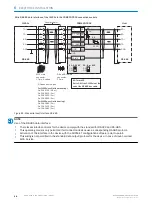
NOTE

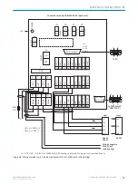
Use of the RS-422 data interface:

The relevant interface drivers for the device comply with the standard for RS-422 and RS-485.

Activation of the interface in the device with the SOPAS ET configuration software (point-to-point).

The connection shown above is configured for operation of the host with permanently activated drivers (often
described as “RS-422 operation”), i.e. not RS-485 bus operation.

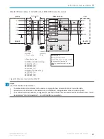
Wire RS-485 data interface of the CLV69x in the CDM490-0001 connection module

CLV69x

CDM490-0001

(Basic card)

Host

Cable 1, e.g. 

No. 2020302 (3 m)

5


.

TD+

TD‒

RD+

RD‒

RD+

RD‒

TD+

TD‒

GND

GND

GND

5

8

8

9

6

7

7

9

24

T+

34

T‒/TxD

25

R+

35

R‒/RxD

36

GND

6

Shield

6

RS-485

RS-485

ON

OFF

S2 : RS 485

ON

OFF

S3: Term 422

S2

ON

S3

OFF

120 Ω


“HOST/AUX/I/O” connection 

1

6

1

10

5

11

15

10 5

6

1

15

11

D-Sub-HD

S3: Term 422

Set to ON if the CLV69x is at the 
end of the RS-485 bus cable.

Figure 73: Wire serial host interface RS-485

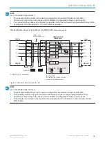
NOTE

Use of the RS-485 data interface:

The relevant interface drivers for the device comply with the standard for RS-422 and RS-485.

This operating mode is only permitted if all connected devices use a corresponding RS-485 protocol.

Activation of the interface in the device with the SOPAS ET configuration software (point-to-point).

This wiring is not permitted in the standard data output/protocol for the device. In case of doubt, contact
SICK Service.

ELECTRICAL INSTALLATION 

6

8014396/ZMG8/2017-07-04 | SICK

O P E R A T I N G   I N S T R U C T I O N S | CLV69x

79

Subject to change without notice

Summary of Contents for CLV69x

Page 1: ...O P E R A T I N G I N S T R U C T I O N S CLV69x Bar code scanners ...

Page 2: ...ible within the limits of the legal determination of Copyright Law Any modifica tion abridgment or translation of this document is prohibited without the express writ ten permission of SICK AG The trademarks stated in this document are the property of their respective owner SICK AG All rights reserved Original document This document is an original document of SICK AG 2 O P E R A T I N G I N S T R ...

Page 3: ...duct ID 12 3 2 Product characteristics 13 4 Transport and storage 20 4 1 Transport 20 4 2 Transport inspection 20 4 3 Storage 20 5 Mounting 21 5 1 Overview of mounting procedure 21 5 2 Scope of delivery 21 5 3 Preparation for mounting 22 5 4 Mounting location 23 5 5 Mounting the device 26 5 6 Mounting with shock mounts optional 26 5 7 Mounting of external components 30 6 Electrical installation 32...

Page 4: ...s 93 10 2 Detailed fault analysis 93 10 3 Status log 93 10 4 SICK Support 94 11 Decommissioning 95 11 1 Disassembly and disposal 95 11 2 Returns 95 12 Technical data 96 12 1 Optics 96 12 2 Performance 96 12 3 Interfaces 97 12 4 Mechanics electronics 97 12 5 Ambient data 98 12 6 Reading field diagrams 98 13 Accessories 125 14 Annex 126 14 1 EU declaration of conformity Certificates 126 14 2 Certifi...

Page 5: ...e device is integrated For information about this refer to the operat ing instructions of the specific machine 1 2 Scope These operating instructions serve to incorporate the device into a customer system Instructions are given by stages for all actions required These instructions apply to all available device variants of the device More detailed information for the identification of the available...

Page 6: ... dimensional drawings and diagrams EU declaration of conformity for the product family Dimensional drawings and 3D CAD dimension models in various electronic for mats These operating instructions available in English and German and in other lan guages if necessary Other publications related to the devices described here Publications dealing with accessories 1 5 Customer service If you require any ...

Page 7: ...der extreme environmental conditions Any use of accessories not specifically approved by SICK AG is at your own risk WARNING Danger due to improper use Any improper use can result in dangerous situations Therefore observe the following information Device should be used only in accordance with its intended use All information in these operating instructions must be strictly observed 2 3 IP technolo...

Page 8: ...ator about the tasks assigned to them and about potential dangers arising from improper action Skilled personnel have the specialist training skills and experience as well as knowledge of the relevant regulations to be able to perform tasks delegated to them and to detect and avoid any potential dangers independently Electricians have the specialist training skills and experience as well as knowl ...

Page 9: ...ods of time may cause damage to the retina The laser radiation is harmless to human skin Do not look into the laser beam intentionally Never point the laser beam at people s eyes If it is not possible to avoid looking directly into the laser beam e g during com missioning and maintenance work suitable eye protection must be worn Avoid laser beam reflections caused by reflective surfaces Be particu...

Page 10: ...ser class 2 NOTE Additional laser warning label If the laser warning label applied to the device is concealed when the device is installed into a machine or paneling the laser beam outlet opening must be suitably labeled For this purpose an additional warning label of the same type must be applied next to the outlet opening Controlling the laser diode When operating properly the device only switch...

Page 11: ...When switching off the device at the most the following data will be lost Application specific parameter sets that were only temporarily stored in the device Last reading result Daily operating hours counter 2 9 Protection of the environment During construction of the device attention was paid to achieving the smallest environ mental impact possible Apart from the housing the device contains no ma...

Page 12: ...de Position Description Characteristic 1 Code reader V principle 2 3 Product family 69 CLV69x 4 Resolution 0 Standard density 1 Low density 2 High density 5 Scanning method reading window orientation 1 0 Line scanner reading window on front 1 Line scanner with oscillating mirror reading window on side 6 Electrical connection 0 60 pin system connection 2 9 Special connection 7 Front screen material...

Page 13: ...ounting holes M4 10 mm deep 2 x for mounting the cloning plug 4 60 pin male connector for connecting a cloning plug 5 Reference point for reading distance housing edge from CLV69x to object 6 Reading window 7 Mark for the direction of rotation of the mirror wheel and counting direction of the read diagnostics date RA Reading Angle 8 Internal impact point rotation point of the variable direction li...

Page 14: ...zer which can be switched off to confirm the device function Application and network setup assistant Read operation modes Start stop operation one bar code bearing object per read pulse Tracking operation Read cycle Pulse sources for start switching inputs data interface com mand auto pulse free CAN Pulse sources for stop read pulse source switching inputs data interface command timer condition Ba...

Page 15: ... 1 e g external read cycle Output 1 e g LED Output 2 e g LED CLV69x xxx0 Serial RS 232 RS 422 485 HOST 1 alternative to Ethernet host port CDM420 0006 Serial Serial e g cable no 6034414 2 m e g cable no 2055419 2 m Configuration Diagnostics SOPAS SOPAS Serial Serial HOST AUX I O AUX 1 HOST 1 1 2 DC 18 V 30 V GND HOST PC e g cable no 2014054 2 m Serial RS 232 AUX 1 alternative to Ethernet AUX port ...

Page 16: ...auto focus area is carried out by selecting the aperture angle the auto focus area and for line scanners with oscillating mirror also by limiting the oscillation amplitude the angle of deflection It is possible to specify among other things the park position preferred position of the focus position from which refocusing is carried out for each reading for the device and a temporal and or spatial d...

Page 17: ...h sides in the case of the line scanner with oscillating mirror The distance configurations are assigned to the switching order via a programmable assignment table NOTE The SOPAS ET configuration software can be used to configure the focus position Project tree CLV6xx parameters read configuration Project tree CLV6xx parameters read configuration oscillating mirror Project tree CLV6xx parameters r...

Page 18: ...ding operation mode In start stop operation there is only ever one object in the reading field during the reading process i e all read codes can be clearly assigned to the object As standard starting and stopping of the reading process are controlled by one or two read cycle sensor s at the start and end of the reading field In this case the distance between the read cycle sensors determines the s...

Page 19: ...ding field a regular cycle is required This is generated by an external incremental encoder which con stantly provides at least one pulse per 1 mm movement in the conveyor direction This provides a clear temporal representation in the device of the route between the read cycle sensor and object release point Jittering when the conveyor technology is starting up or in the event of slowing down when...

Page 20: ...lows Do not accept the delivery or only do so conditionally Note the scope of damage on the transport documents or on the transport compa ny s delivery note File a complaint NOTE Complaints regarding defects should be filed as soon as these are detected Damage claims are only valid before the applicable complaint deadlines 4 3 Storage Store the device under the following conditions Recommendation ...

Page 21: ...ked or broken Device with connector Over rotation of the connector cracks or being torn from the housing Device with fixed cable Damage to the cable outlet or cable itself 5 2 Scope of delivery The delivery of the device includes the following components Table 4 Scope of delivery Item Component Comments 1 Device Depending on version 1 Printed safety note Additional scope of delivery NOTE The addit...

Page 22: ...M6 screws NOTE The screws are used for mounting the device on a mounting device supplied by the user Screw length is dependent on the mounting base wall thickness of the bracket When using an optional SICK bracket the screws for mounting the device are included with delivery Tool and tape measure 5 3 2 Mounting device The device is mounted on the bracket using two M6 blind hole threads that are in...

Page 23: ...ied cylinder head screws replace the screws from mounting kit 2 or 3 5 4 Mounting location When selecting the mounting location the following factors are significant b Basic allocation of the scan line to the bar code b Reading distance to the bar code and aperture angle α b Angle alignment of the device b Avoidance of surface reflections b Count direction of the reading angle position of the bar ...

Page 24: ...s see Reading field condi tions page 98 5 4 3 Angle alignment of the device The optimum alignment of the device is achieved when the scan line crosses the stripes of the bar code as close to a right angle as possible tilt and inclination Possi ble reading angles that can arise between scan line and bar code at all three levels in the area must be taken into account In order to prevent surface refl...

Page 25: ...rror Figure 15 Avoiding surface reflections on the example line scanner angle between light emit ted and bar code tilting away from vertical 5 4 5 Count direction of the reading angle and the code angle The device can scan and decode several bar codes at each reading At the same time the location specific reading diagnostics data are determined for each of them The reading angle starting from the ...

Page 26: ...observer and is aligned as near as possible to being parallel to the bar code surface For a device with the reading window at the side ensure that the side panel with the LEDs points in the direction of the observer and is aligned almost parallel to the bar code surface In a device with oscillating mirror the wide side panel rear of the oscillating mirror is almost parallel to the bar code surface...

Page 27: ...nsured that the holding plate the mounting bracket is screwed directly to the device and the shock attenuation is applied as close as possible to the device The shock mounts must always be mounted horizontally over the scanner in order to achieve an optimum shock absorp tion Figure 17 Angle bracket with shock mount During mounting of an oscillating mirror device the mounting bracket with integrate...

Page 28: ... all axis directions of the device This applies in particular in the event of slanting installation b Set the length of the feed lines according to the travel in order to ensure strain relief Permissible installation variants Three installation variants are permitted 1 Mounting of line scanner horizontal reading line mounting bracket with inte grated vibration shock attenuation 5 MOUNTING 28 O P E...

Page 29: ...ertical reading line ball joint bracket and mounting bracket with integrated vibration shock attenuation MOUNTING 5 8014396 ZMG8 2017 07 04 SICK O P E R A T I N G I N S T R U C T I O N S CLV69x 29 Subject to change without notice ...

Page 30: ...s the AUX interface RS 232 57 6 kBd of the device via the connection module then the connection mod ule must be installed no more than a 3 m length of cable from the device 1 Mount the connection module in the vicinity of the device 2 Mount the connection module in such a way that the open module can be accessed at all times NOTE Detailed information on mounting and electrical installation can be ...

Page 31: ...7 3 Mounting incremental encoder An incremental encoder is needed during the separation of bar codes of the same code type and with identical contents The incremental pulses must originate from the area of the conveying line on which the device is reading 1 Mount suitable incremental encoders in the vicinity of the device Optimally the incremental encoder is mounted against the running direction o...

Page 32: ...rcuits connected to the device must be designed as SELV circuits SELV Safety Extra Low Voltage Protect the device with a separate fuse type specific max 2 A unheated or 4 A heated at the start of the supply circuit NOTE Layout of data cables Use screened data cables with twisted pair wires Implement the screening design correctly and completely To avoid interference e g from switching power suppli...

Page 33: ...evice is designed and tested for electrical safety in accordance with EN 60950 1 It is connected to the peripheral devices power supply any local reading pulse sen sor s PLC via shielded cables The cable shield for the data cable for example rests against the metal housing of the device The device can either be grounded through the cable shield or through one of the threaded mounting holes If the ...

Page 34: ...he setting up of local islands and connecting them using commercially available electro optical signal isolators is recommended This measure achieves a high degree of resistance to electromagnetic interference while at the same time complying with all the requirements of EN 60950 1 grounding point 1 grounding point 2 Electro optical signal isolator Electro optical signal isolator e g PLC Power sup...

Page 35: ... also guar antee the required level of insulation Under certain circumstances a tangible potential can develop between the insulated metal housings and the local ground potential 6 3 Wiring notes NOTICE Faults due to incorrect wiring Incorrect wiring may result in operational faults For data transmission use only screened cables with twisted pair wires Follow the wiring notes precisely NOTE Preass...

Page 36: ... 21 Sensor 3 IN 13 1 Sensor 4 IN 23 1 Sensor 4 IN 23 1 Sensor 4 IN 23 1 Sensor 5 IN 33 1 Sensor 6 IN 43 1 Result 12 Result 12 Result 22 Result 22 Result 32 Result 32 4 Result 42 Result 42 4 Serial AUX Serial AUX Serial AUX Serial AUX Serial Host Serial Host CAN 1 CAN 1 CAN 1 CAN 1 CAN 1 CAN 1 CAN 2 CAN 2 CAN 2 Ethernet Ethernet Ethernet DC 24 V out5 DC 24 V out5 1 Switching input 2 Switching outpu...

Page 37: ...nation CLV480 490 CLX490 3 Pin 5 male female connector connected 4 Do not use 1 Pin 1 male female connector connected 2 Pin 5 male female connector connected 3 Do not use Connection HOST AUX Connection I O 6 1 10 5 11 15 I O connection Vs Imax in 1 A D sub HD female connector 15 pin Reserved4 Result 4 Result 3 Sensor 6 IN 4 2 Result 2 Result 1 Sensor 1 Sensor2 Sensor 2 IN 0 2 Sensor 4 IN 2 2 SensG...

Page 38: ...38 21 12 0 22 49 71 0 60 82 99 Cloning plug All lengths in mm View cloning plug with modular hood Modular hood with connecting cables for CLV69x without heating Figure 25 Cloning plug A D Sub HD Power Serial Data I O CAN 1 2 6 ELECTRICAL INSTALLATION 38 O P E R A T I N G I N S T R U C T I O N S CLV69x 8014396 ZMG8 2017 07 04 SICK Subject to change without notice ...

Page 39: ... 10 11 12 13 14 15 16 17 Connection Ethernet Connection CAN 1 Connection HOST AUX I O no 2062452 17 16 10 11 12 15 14 6 5 4 13 7 8 9 1 2 3 1 For CLV69x xxx0 without heating both contacts suitable for connection of the supply voltage 2 For CLV69x xxx1 with heating only this contact suitable for connection of the supply voltage Sensor 1 and 2 digital switching inputs Result 1 4 digital switching out...

Page 40: ... RS 232 AUX Vs OUT Sensor 4 IN 2 GND pin designation CLV480 490 CLX490 3 2 1 4 5 CAN 1 OUT connection Vs Imax out 4 A M12 female connector 5 pin A coded 4 2 3 5 1 Shield GND Vs CAN1_L CAN1_H no 2062453 Figure 28 Cloning plug C M12 Power Serial AUX IO CAN 1 12 0 21 38 60 82 99 18 0 13 7 18 20 All lengths in mm C CAN 1 IN Blower AUX CAN 1 OUT Figure 29 Cloning plug C M12 Power Serial AUX IO CAN 1 6 ...

Page 41: ...nnector 5 pin A coded Connection CAN 2 Connection CAN 1 Connection Blower AUX 4 2 3 5 1 3 2 1 4 5 RxD RS 232 AUX TxD RS 232 AUX Vs OUT fan Sensor 4 IN 2 GND pin designation CLV480 490 CLX490 no 2062454 Figure 30 Cloning plug D M12 Power Serial AUX IO CAN 1 2 12 0 21 38 60 82 99 18 0 13 7 18 20 All lengths in mm D CAN 1 Blower AUX CAN 2 Figure 31 Cloning plug D M12 Power Serial AUX IO CAN 1 2 ELECT...

Page 42: ...out 4 A M12 female connector 5 pin A coded 4 2 3 5 1 Shield GND Vs CAN1_L CAN1_H no 2074708 4 3 2 1 TD TD RD RD 4 3 2 1 M12 female connector 4 pin D coded Figure 32 Cloning plug E M12 Power Ethernet CAN 1 12 0 21 38 60 82 99 18 0 13 7 18 20 All lengths in mm E CAN 1 IN Ethernet CAN 1 OUT Figure 33 Cloning plug E M12 Power Ethernet CAN 1 6 ELECTRICAL INSTALLATION 42 O P E R A T I N G I N S T R U C ...

Page 43: ... Ethernet connection Connection CAN 2 Connection CAN 1 Connection Ethernet no 2074710 4 3 2 1 TD TD RD RD 4 3 2 1 M12 female connector 4 pin D coded Figure 34 Cloning plug F M12 Power CAN 1 Ethernet CAN 2 12 0 21 38 60 82 99 18 0 13 7 18 20 All lengths in mm F CAN 1 Ethernet CAN 2 Figure 35 Cloning plug F M12 Power CAN 1 Ethernet CAN 2 ELECTRICAL INSTALLATION 6 8014396 ZMG8 2017 07 04 SICK O P E R...

Page 44: ...36 Connection of the device to the CDB650 204 connection module CDM420 0006 UV Sensor 2 Host 1 serial Aux 1 serial Result 2 Result 1 CAN Sensor 2 Sensor 1 Ext input 2 Ext input 1 Sensor 1 AUX PLC CAN bus PLC Result 1 Result 2 PLC PLC Ext output 1 Ext output 2 Connection module CDM420 0006 Other functions HOST 1 serial AUX 1 serial RS 232 CMC600 For the additional use of the external switching inpu...

Page 45: ...ltage to devices without heating NOTICE Devices with integrated heating may only be connected to the supply voltage via the 5 pin M12 male connector CAN 1 of the cloning plug In order to do this the steps for the commissioning of devices with integrated heating must be followed The device must be connected to a power supply unit with the following properties Supply voltage DC 24 V 20 stabilized sa...

Page 46: ...The following standards must be observed in Germany DIN VDE 0100 part 430 DIN VDE 0298 part 4 and or DIN VDE 0891 part 1 The infeed of the supply voltage is carried out using a SICK connection module or the customer s voltage supply 6 6 2 Wiring data interfaces Wiring Ethernet interface 1 Connect the device to the Ethernet connection of the PC via the adapter cable 2 Set up communication via SOPAS...

Page 47: ...this can be found in the operating instructions for the relevant module 6 6 3 Wiring the CAN interface If the wiring of the CAN interface is carried out via a connection module then the rele vant operating instructions of the module used must be followed 6 6 4 Wiring digital switching inputs Physical switching inputs on the device The physical switching inputs can be used for starting and or endin...

Page 48: ... input with external triggered PNP sensor 1 Supply voltage Us 2 Signal line e g Sensor 2 3 SensGND 4 GND Extension additional logical switching inputs in the device in the case of physical external switching inputs on the optional connection module Thanks to the optional CMC600 parameter memory module the two external switching inputs External input 1 and External input 2 on the relevant terminals...

Page 49: ... Switching output Result 1 or Result 2 2 Output signal 3 Output voltage Vout 4 With an inductive load Sweep out circuit attach a freewheeling diode directly to the load For pin assignment see respective device Extension additional logical switching outputs in the device in the case of physical external switching outputs on the optional connection module Thanks to the optional CMC600 parameter memo...

Page 50: ...electric sensor UV Out GND Result 1 PLC GND Result 2 to the PC to the CLV69x xxx0 without heating Pin 2 RxD 3 TxD 5 GND Host TD TD RD RD TxD Host RxD GND GND RS 232 RS 422 UV DC 18 V 30 V for CLV69x xxx0 without heating at terminal UIN UIN after switch S1 protected with internal fuse F 2 A T F 17 16 10 11 12 15 14 6 5 4 13 7 8 9 1 2 3 SENSOR 50 51 52 53 54 RES OUT 3 RES OUT 4 Ext Illum TR L GND 20...

Page 51: ...ng protected by external fuse provided by user 2 A T F 17 16 10 11 12 15 14 6 5 4 13 7 8 9 1 2 3 SENSOR 50 51 52 53 54 RES OUT 3 RES OUT 4 Ext Illum TR L GND 20 21 22 23 24 GND RES OUT 1 RES OUT 2 EXT OUT 1 EXT OUT 2 10 11 12 13 14 15 16 17 18 U IN U IN SGND SGND SGND EXT IN 1 SENS IN 1 SENS IN 2 EXT IN 2 RS 232 For the additional use of the external switching inputs and outputs the optional CMC60...

Page 52: ...12 15 14 6 5 4 13 7 8 9 1 2 3 1 connection cable 1 1 no 6052286 2 m no 6051194 3 m no 6051195 5 m Switch S1 ON Supply voltage UIN connected via fuse as UIN to CDB650 204 and CLV69x Voltage UIN can also be tapped at terminal 11 and 14 OFF CDB650 204 and CLV69x separated from supply voltage Recommended setting for all connection work Cloning plug no 2062452 Max 2 A Fext Connection cable1 Figure 45 W...

Page 53: ... 16 10 11 12 15 14 6 5 4 13 7 8 9 1 2 3 GND Shield 1 2 17 16 10 11 12 15 14 6 5 4 13 7 8 9 1 2 3 M12 17 pin A coded F Switch S1 ON Supply voltage UIN connected via fuse as UIN to CDB650 204 and CLV69x Voltage UIN can also be tapped at terminal 11 and 14 OFF CDB650 204 and CLV69x separated from supply voltage Recommended setting for all connection work 2 Pin 2 in the CLV69x xxx1 with heating not co...

Page 54: ...16 10 11 12 15 14 6 5 4 13 7 8 9 1 2 3 17 16 10 11 12 15 14 6 5 4 13 7 8 9 1 2 3 For CLV69x xxx0 without heating no 6052286 2 m no 6051194 3 m no 6051195 5 m For CLV69x xxx1 with heating no 6053230 2 m no 6053231 3 m no 6053232 5 m 1 Dependent on type Connection cable 1 11 Figure 47 Wire serial host interface RS 232 6 ELECTRICAL INSTALLATION 54 O P E R A T I N G I N S T R U C T I O N S CLV69x 8014...

Page 55: ...69x xxx0 without heating no 6052286 2 m no 6051194 3 m no 6051195 5 m For CLV69x xxx1 with heating no 6053230 2 m no 6053231 3 m no 6053232 5 m 1 Dependent on type Figure 48 Wire serial host interface RS 422 NOTE Use of the RS 422 data interface The relevant interface drivers for the device comply with the standard for RS 422 and RS 485 Activation of the interface in the device with the SOPAS ET c...

Page 56: ...1195 5 m For CLV69x xxx1 with heating no 6053230 2 m no 6053231 3 m no 6053232 5 m 1 Dependent on type Connection cable 1 11 Figure 49 Wire serial host interface RS 485 NOTE Use of the RS 485 data interface The relevant interface drivers for the device comply with the standard for RS 422 and RS 485 This operating mode is only permitted if all connected devices use a corresponding RS 485 protocol A...

Page 57: ...ble 1 11 Connection cable 1 11 CAN CAN CAN including CAN including CAN including CAN including CAN Connection and looping through of the supply voltage and connection of the read cycle sensor to e g master neglected here Switch ON OFF S2 TermCAN Serial host interface Ethernet Host Port 422 485 S6 RS Wire CLV69x in the CDB650 204 connection module for SICK CAN SENSOR network Ethernet Ethernet For C...

Page 58: ...ts connected with GND of the CDB650 204 CLV69x OFF Sensors on switching inputs of the CDB650 204 CLV69x connected volt free Reference potential valid for all switching inputs SENS IN 1 2 and optionally EXT IN1 and 2 CDB650 204 CLV69x Terminal X 10 13 Name SENS IN 1 SENS IN 2 Pin Y 10 15 Pin Y 10 15 Sensor Z Sensor 1 Sensor 2 Functional allocation for switching inputs via SOPAS ET configuration sof...

Page 59: ...D 18 SGND 8 Shield 11 UIN X Out GND S3 e g photoelectric sensor UV ext Name CMC600 UIN No YES S4 CMC ON OFF S3 SGND GND Ue SensGND Switch S3 SGND GND ON GND of the switching inputs connected with GND of the CDB650 204 CMC600 OFF Sensors on switching inputs of the CDB650 204 CMC600 connected volt free Reference potential valid for all switching inputs SENS IN 1 2 and optionally EXT IN1 and 2 CDB650...

Page 60: ...ng no 6053230 2 m no 6053231 3 m no 6053232 5 m 2 Pin 2 in the CLV69x xxx1 with heating not connected 1 Dependent on type Specifications of the switching outputs Result 1 4 Functional allocation for switching outputs via SOPAS ET configuration software Connection cable 1 11 Logic Properties Electrical values PNP switching to supply voltage UV CLV69x default Result 1 Device Ready static logic activ...

Page 61: ... to its physical outputs EXT OUT 1 and 2 in the CDB650 204 External output 1 output 2 Z Name 22 GND 6 Shield CDB650 204 CLV69x Terminal Z Name Output 23 24 EXT OUT 1 EXT OUT 2 External output 1 External output 2 Functional allocation for switching outputs via SOPAS ET configuration software Logic Properties Electrical values PNP switching to supply voltage UIN default no function logic not inverte...

Page 62: ...t 2 S1 POWER ON OFF S2 S3 S4 S6 ON OFF ON OFF RS485 Term422 TermCAN SGND GND 1 5 6 9 to PC Pin 2 RxD 3 TxD 5 GND Result 1 PLC GND Result 2 External sensor for reading cycle e g photoelectric sensor UV Out GND Host TD TD RD RD TxD Host RxD GND GND RS 232 RS 422 RS 485 F to CLV69x xxx0 without heating For additional use of external switching inputs and outputs the optional CMC600 parameter memory mo...

Page 63: ... S6 ON OFF ON OFF RS485 Term422 TermCAN SGND GND 1 5 6 9 to PC Pin 2 RxD 3 TxD 5 GND Result 1 PLC GND Result 2 External sensor for reading cycle e g photoelectric sensor UV Out GND Host TD TD RD RD TxD Host RxD GND GND RS 232 RS 422 RS 485 F to CLV69x xxx1 with heating For additional use of external switching inputs and outputs the optional CMC600 parameter memory module is required UV DC 21 6 V 2...

Page 64: ...1 15 Switch S1 ON supply voltage UV 24 V switched via fuse as UV 24 V to CDM420 0006 and CLV69x UV 24 V can also be engaged at terminal 29 and 39 OFF CDM420 0006 and CLV69x separated from supply voltage Recommended position for all connection types For CLV69x xxx0 without heating No 2049764 0 9 m no 2055419 2 m no 2055420 3 m No 2055859 5 m 1 Adapter cable Cloning plug No 2062452 HOST AUX I O conn...

Page 65: ...dapter cable No 6053224 5 m No 6053225 10 m Connection CAN 1 4 2 3 5 1 Switch S1 ON supply voltage UV 24 V switched via fuse as UV 24 V to CDM420 0006 and CLV69x UV 24 V can also be engaged at terminal 29 and 39 OFF CDM420 0006 and CLV69x separated from supply voltage Recommended position for all connection types Adapter cable1 DC 21 6 V 28 8 V red Gray Blue 2 Pin 2 in CLV69x xxx1 with heating not...

Page 66: ...5 ON OFF S3 Term 422 S2 OFF 485 17 16 10 11 12 15 14 6 5 4 13 7 8 9 1 2 3 For CLV69x xxx0 without heating No 2049764 0 9 m No 2055419 2 m No 2055420 3 m No 2055859 5 m For CLV69x xxx1 with heating No 2061480 2 m No 2061605 3 m No 2061481 5 m 1 Dependent on type 6 1 10 5 11 15 Adapter cable1 Figure 59 Wire serial host interface RS 232 6 ELECTRICAL INSTALLATION 66 O P E R A T I N G I N S T R U C T I...

Page 67: ... 5 m 1 Dependent on type S3 Term 422 Set to ON if termination of the RS 422 receiver in the CLV69x is necessary to improve the signal to interference ratio on the cable Adapter cable1 Figure 60 Wire serial host interface RS 422 NOTE Use of the RS 422 data interface The relevant interface drivers for the device comply with the standard for RS 422 and RS 485 Activation of the interface in the device...

Page 68: ...o 2061481 5 m 1 Dependent on type S3 Term 422 Set to ON if the CLV69x is at the end of the RS 485 bus cable Adapter cable1 Figure 61 Wire serial host interface RS 485 NOTE Use of the RS 485 data interface The relevant interface drivers for the device comply with the standard for RS 422 and RS 485 This operating mode is only permitted if all connected devices use a corresponding RS 485 protocol Act...

Page 69: ...CAN 1 among others Connection and looping of the supply voltage and connection of the read cycle sensor e g to host is neglected here Switch ON OFF S4 TermCAN Serial host interface Ethernet Host Port ON OFF S2 RS485 Wire CLV69x in the CDM420 0006 connection module for SICK CAN SENSOR network CAN_H CAN1_H CLV69x CAN_L CAN1_L CLV69x S4 TermCAN TermCAN1 For CLV69x xxx0 without heating No 2049764 0 9 ...

Page 70: ... In 1 and 2 Shield D Sub HD female connector 15 pin M12 male connector 17 pin A coded GND X Name 37 SGND 6 Shield 39 24 V Ue max 32 V 24 V CDM420 0006 GND S6 ON OFF S6 SGND GND Shield 38 Sensor 1 37 SGND 6 Shield 39 24 V b Sensor connected volt free and externally supplied 24 V CDM420 0006 PNP sensor UV GND Out GND S6 e g photoelectric sensor ON OFF S6 SGND GND UV ext Shield 38 Sensor 1 37 SGND 6 ...

Page 71: ...Low Ue 2 V Ie 0 3 mA High 6 V Ue 30 V 0 7 mA Ie 5 mA Switching behavior Properties Electrical values a Switch supplied by CDM420 0006 CDM420 0006 Ue GND S6 CMC600 ON OFF S6 SGND No YES S8 CMC 17 SGND 8 Shield 39 24 V 18 Aux In 1 24 V SensGND CDM420 0006 PNP sensor UV GND Out GND S6 e g photoelectric sensor UV ext Ue CMC600 b Sensor connected volt free and externally supplied No YES S8 CMC ON OFF S...

Page 72: ...LV69x xxx1 with heating not connected Characteristic data of Result 1 and 2 switching outputs PNP switching to supply voltage UV CLV69x default settings Result 1 device ready static logic active high Result 2 good read 100 mm logic active high Short circuit protected temperature protected Not electrically isolated from supply voltage 24 V 0 V Ua UV Guaranteed UV 1 6 V Ua UV at Ia 100 mA Switching ...

Page 73: ...oltage 24 V 0 V Ua UV Guaranteed UV 1 5 V Ua UV at Ia 100 mA Switching behavior Properties Electrical values The CLV69x issues the output states of its External output 1 and 2 logical outputs via its serial AUX interface Via the connecting cable the CMC600 automatically adopts the statuses and translates them to its physical AUX Out 1 and 2 outputs in the CDM420 0006 using software CDM420 0006 CLV...

Page 74: ...485 Term422 TermCAN ON OFF S5 TermCAN2 To CLV69x xxx0 HOST AUX 1 5 6 9 To PC Pin 2 RxD 3 TxD 5 GND 21 22 23 24 25 26 27 28 29 T R 24 V GND GND GND Pin14 n u Pin11 n u CAN_H CAN_L Host TD TD RD RD TxD Host RxD GND GND RS 232 RS 422 RS 485 F CAN_H CAN1_H CAN_L CAN1_L UV Max 2 A Fext UV DC 18 V 30 V for CLV69x xxx0 without heating at terminal 24 V 24 V after switch S1 protected by internal fuse F Fig...

Page 75: ...AN2 To CLV69x xxx1 HOST AUX 1 5 6 9 To PC Pin 2 RxD 3 TxD 5 GND 21 22 23 24 25 26 27 28 29 T R 24 V Pin4 n u Pin14 n u Pin11 n u GND GND GND CAN_H CAN_L Host TD TD RD RD TxD Host RxD GND GND RS 232 RS 422 RS 485 F CAN_H CAN1_H CAN_L CAN1_L UV Max 4 A Fext UV DC 21 6 V 28 8 V for CLV69x xxx1 with heating protected by external fuse provided by user Voltage supply to CLV69x xxx1 with heating Figure 6...

Page 76: ...IN 3 IN 1 IN 4 Sensor 1 IN 0 71 72 73 74 75 76 GND Reserve GND Reserve GND GND External sensor for reading cycle e g photoelectric sensor UV Out GND IN 0 1 2 3 4 Sensor OUT On basic card 10 1 6 5 11 15 LED S1 ON OFF SGND Figure 69 Wiring overview part 2 I O map top right 1 switching input used 6 ELECTRICAL INSTALLATION 76 O P E R A T I N G I N S T R U C T I O N S CLV69x 8014396 ZMG8 2017 07 04 SIC...

Page 77: ... O connection CLV69x xxx0 without heating DC 18 V 30 V Max 2 A F UV DC 18 V 30 V at terminal 24 V UV at terminal 24 V after switch S1 protected by internal fuse F Switch S1 ON supply voltage UV 24 V switched via fuse as UV 24 V to CDM490 0001 and CLV69x UV 24 V can also be engaged on terminal 29 of the basic card as well as on terminal 51 53 of the I O card OFF CDM490 0001 and CLV69x separated fro...

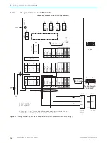
Page 78: ... connection module CLV69x Host Cable 1 e g No 2020302 3 m 5 TD TD RD RD RD RD TD TD GND GND GND 5 8 8 9 6 7 9 6 7 24 T 34 T TxD 25 R 35 R RxD 36 GND 6 Shield RS 422 RS 422 ON OFF S2 RS 485 ON OFF S3 Term 422 S2 OFF S3 OFF 120 Ω 1 HOST AUX I O connection 1 6 1 10 5 11 15 10 5 6 1 15 11 D Sub HD S3 Term 422 Set to ON if termination of the RS 422 receiver in the CLV69x is necessary to improve the sig...

Page 79: ...S 485 RS 485 ON OFF S2 RS 485 ON OFF S3 Term 422 S2 ON S3 OFF 120 Ω 1 HOST AUX I O connection 1 6 1 10 5 11 15 10 5 6 1 15 11 D Sub HD S3 Term 422 Set to ON if the CLV69x is at the end of the RS 485 bus cable Figure 73 Wire serial host interface RS 485 NOTE Use of the RS 485 data interface The relevant interface drivers for the device comply with the standard for RS 422 and RS 485 This operating m...

Page 80: ...D RD TD RS 232 RS 422 T TxD R RxD T R 26 Connecting cable1 Connecting cable1 Connecting cable1 Connecting cable1 CAN CAN CAN CAN 1 among others CAN 1 among others CAN 1 among others CAN 1 among others Connection and looping of the supply voltage and connection of the read cycle sensor e g to host is neglected here Switch ON OFF S4 TermCAN Serial host interface Ethernet Host Port ON OFF S2 RS485 Wi...

Page 81: ...es Electrical values Switch S1 SGND ON connect GND of the switching inputs to the GND of the CDM490 0001 CLV69x OFF sensors connected volt free to switching inputs on the CDM490 0001 CLV69x Reference potential valid for all Sensor 1 6 switching inputs and optionally Shield 1 E g no 2020302 3 m GND Shield X Name 54 SGND 6 Shield 51 24 V X Name 54 SGND 6 Shield 51 24 V Ue max 32 V a Schema switch su...

Page 82: ...mm logic active high Result 3 no function assigned Result 4 no function assigned Short circuit protected temperature protected Not electrically isolated from UV 24 V 0 V Ua UV Guaranteed UV 1 6 V Ua UV at Ia 100 mA Switching behavior Properties Electrical values 2 I O connection 2 6 1 10 5 11 15 10 5 6 1 15 11 D Sub HD CDM490 0001 CLV69x Terminal Z 41 42 43 44 Name Result 1 Result 2 Result 3 Resul...

Page 83: ...ry areas of the device with the data recorder Diagnostics for the system 7 2 2 Installing SOPAS ET NOTE The configuration software SOPAS ET the current system prerequisites for the PC and the instructions for downloading can be found online at b www sick com SOPAS_ET 1 Start the PC and download the latest version at www sick com SOPAS_ET 2 If installation does not start automatically launch setup ...

Page 84: ...ing memory of the bar code scanner Permanently saved parameter set Saved project file sopas with archived parameter set Permanently saved parameter set Factory default of the bar code scanner Opened project file with current parameter set Parameter memory module CMC600 and or optional Figure 77 Saving the parameter set and configuration with SOPAS ET Parameter set in the main memory of the device ...

Page 85: ...lace objects with bar codes one after the other into the reading range of the device see Technical data page 96 5 Check the reading result with the SOPAS ET configuration software 6 When doing so place objects at different positions angles in the reading field and ensure that the limit values for the permitted reading angles are not exceeded see Angle alignment of the device page 24 7 Align the de...

Page 86: ...n line Figure 79 Appearance of the scan line in Adjusting Mode This function is only available under adjustment mode in Quickstart in the Authorized customer level Code configuration In the factory default setting the device decodes the following code types Code 39 2 5 interleaved Code 128 family You can activate further code types and set other decoder properties Device Tree Parameters Code Confi...

Page 87: ...the Sensor 1 switching input select the setting Sensor 1 Device tree Parameters Object trigger control Test and if necessary modify the specified settings when operating the system under real conditions COMMISSIONING 7 8014396 ZMG8 2017 07 04 SICK O P E R A T I N G I N S T R U C T I O N S CLV69x 87 Subject to change without notice ...

Page 88: ...e Data transmission via CAN interface status of the internal termi nation of the cloning plug all existing terminations are active Ö purple Data transmission via CAN interface status of the internal termi nation of the cloning plug not all existing terminations are active LNK TX O green Physical Ethernet connection Ö green Data traffic via Ethernet O illuminated Ö flashing Operating button and sta...

Page 89: ...at the device with the SOPAS ET configuration software Protection of the parameter set as a configuration file on the PC in SOPAS ET Access to the device via AUX interface USB or Ethernet As an alternative to the SOPAS ET configuration software command strings are available upon which the operator interface of the configuration software is also based These are also for the triggering of device fun...

Page 90: ...ly relevant in harsh operating environments dust abrasion damp fingerprints etc The reading window lens must be kept clean and dry during operation NOTICE Equipment damage due to improper cleaning Improper cleaning may result in equipment damage Only use recommended cleaning agents Never use sharp objects for cleaning Cleaning the reading window NOTICE Damage to the Reading Window Reduced reading ...

Page 91: ...he device for the duration of the cleaning operation If this is not possi ble use suitable laser protection goggles These must absorb radiation of the devi ce s wavelength effectively b Glass lens Remove dust from the reading window using a soft clean brush If nec essary also clean the reading window with a clean damp lint free cloth and a mild anti static glass cleaning agent b Plastic lens Clean...

Page 92: ...ation from the optical effect surfaces of external sensors Figure 81 Cleaning the external optical sensors read pulse encoder 9 MAINTENANCE 92 O P E R A T I N G I N S T R U C T I O N S CLV69x 8014396 ZMG8 2017 07 04 SICK Subject to change without notice ...

Page 93: ... on the sensor housing see Opti cal displays and control elements page 88 include Operational readiness Ready Reading result status Good Read or No Read Hardware fault Firmware download status Connection status of the device The LED display can indicate any errors or faults with this Further information for this can be found in the system information 10 2 2 System information The device outputs fa...

Page 94: ...t be repaired by the user Interrupting or modifying the device will invalidate any warranty claims against SICK AG Rapid replacement of a device by the user is however possible see Disassembly and disposal page 95 see Disassembly and disposal page 95 b Where a fault cannot be rectified make contact with the SICK Service department To find your agency see the final page of this document NOTE Before...

Page 95: ...be disposed of in an environmentally friendly manner in accordance with the applicable country specific waste disposal regu lations As they are categorized as electronic waste the device must never be disposed of with household waste 11 2 Returns b Do not dispatch devices to the SICK Service department without consultation NOTE To enable efficient processing and allow us to determine the cause qui...

Page 96: ...ont end 60 Oscillating mirror 50 Scanning frequency 400 Hz 1200 Hz Code resolution 0 25 mm 1 0 mm 0 35 mm 1 2 mm 0 17 mm 0 4 mm Reading distance 500 mm 2100 mm 500 mm 2200 mm 400 mm 1600 mm type dependent Oscillating mirror functions Fixed adjustable position oscillating variable or fixed amplitude one shot Oscillation frequency 0 5 Hz 4 Hz Angle of deflection 20 20 can be adjusted using software ...

Page 97: ...xx DeviceNet Optional via external connection module CDM CDF Switching inputs Cloning plug no 2062450 6x Cloning plug no 2062452 2x Ue max 30 V Ie max 5 mA Opto decoupled reverse polarity protected adjustable debounce time Switching outputs Cloning plug no 2062450 4x Cloning plug no 2062452 4x Ua UV 1 6 V Ia 100 mA typical Short circuit protected temperature protected not electrically isolated fro...

Page 98: ...950 1 2006 04 A11 2009 03 A1 2010 03 A12 2011 02 Weight Line scanner 1500 g Line scanner with oscillating mirror 2200 g Dimensions L x W x H Front end 117 mm x 117 mm x 94 mm Oscillating mirror 182 mm x 128 mm x 97 mm Enclosure rating IP 65 12 5 Ambient data CLV690 0 1 Standard Density CLV691 0 1 Low Den sity CLV692 0 1 High Density Interference emission EN 61000 6 4 2007 01 A1 2011 02 Immunity to...

Page 99: ...g frequency characteristic curve page 120 Scanning procedure line scanner with oscillating mirror CLV69x type Resolution Diagram Page CLV690 1xxx Standard Density Reading field height resolution over reading distance page 105 Min and max reading distance DOF for resolution 0 35 mm aperture angle 40 page 106 Min and max reading distance DOF for resolution 0 35 mm aperture angle 50 page 107 Min and ...

Page 100: ...1000 1300 1600 1900 2200 Reading distance in mm Resolution a 0 30 mm c 0 50 mm b 0 35 mm Figure 82 CLV690 0xxx Standard Density reading field height depending on the reading distance and resolution 12 TECHNICAL DATA 100 O P E R A T I N G I N S T R U C T I O N S CLV69x 8014396 ZMG8 2017 07 04 SICK Subject to change without notice ...
Page 101: ... reading distance Minimum reading distance Reading areas from approx 1540 mm Typical focus position values Resolution 0 35 mm Aperture angle 40 Figure 83 CLV690 0xxx Standard Density min and max radial reading distance depending on focus position with resolution 0 35 mm and aperture angle a 40 TECHNICAL DATA 12 8014396 ZMG8 2017 07 04 SICK O P E R A T I N G I N S T R U C T I O N S CLV69x 101 Subje...

Page 102: ...nce mm Focus position mm Resolution 0 35 mm Aperture angle 56 Maximum reading distance Minimum reading distance Figure 84 CLV690 0xxx Standard Density min and max radial reading distance depending on focus position with resolution 0 35 mm and aperture angle a 56 12 TECHNICAL DATA 102 O P E R A T I N G I N S T R U C T I O N S CLV69x 8014396 ZMG8 2017 07 04 SICK Subject to change without notice ...
Page 103: ...nce mm Focus position mm Resolution 0 50 mm Aperture angle 40 Maximum reading distance Minimum reading distance Figure 85 CLV690 0xxx Standard Density min and max radial reading distance depending on focus position with resolution 0 50 mm and aperture angle a 40 TECHNICAL DATA 12 8014396 ZMG8 2017 07 04 SICK O P E R A T I N G I N S T R U C T I O N S CLV69x 103 Subject to change without notice ...
Page 104: ...nce mm Focus position mm Resolution 0 50 mm Aperture angle 56 Maximum reading distance Minimum reading distance Figure 86 CLV690 0xxx Standard Density min and max radial reading distance depending on focus position and resolution 0 50 mm and aperture angle a 56 12 TECHNICAL DATA 104 O P E R A T I N G I N S T R U C T I O N S CLV69x 8014396 ZMG8 2017 07 04 SICK Subject to change without notice ...

Page 105: ... distance and resolution 12 6 4 Standard Density reading performance data line scanner with oscillating mirror 600 400 400 700 1300 1000 1600 1900 2200 200 0 200 400 600 Reading field height in mm Resolution a 0 30 mm b 0 35 mm c 0 50 mm a b c Reading distance in mm Figure 88 CLV690 1xxx Standard Density reading field height depending on the reading distance and resolution TECHNICAL DATA 12 801439...

Page 106: ...n mm Resolution 0 35 mm Aperture angle 40 Maximum reading distance Minimum reading distance Reading areas from approx 1440 mm Typical focus position values Figure 89 CLV690 1xxx Standard Density min and max radial reading distance depending on focus position with resolution 0 35 mm and aperture angle α 40 12 TECHNICAL DATA 106 O P E R A T I N G I N S T R U C T I O N S CLV69x 8014396 ZMG8 2017 07 0...

Page 107: ...ngle 50 Minimum reading distance Standard Density line scanner with oscillating mirror CLV690 1xxx Maximum reading distance Figure 90 CLV690 1xxx Standard Density min and max radial reading distance depending on focus position with resolution 0 35 mm and aperture angle α 50 TECHNICAL DATA 12 8014396 ZMG8 2017 07 04 SICK O P E R A T I N G I N S T R U C T I O N S CLV69x 107 Subject to change without...

Page 108: ...ngle 40 Maximum reading distance Minimum reading distance Standard Density line scanner with oscillating mirror CLV690 1xxx Figure 91 CLV690 1xxx Standard Density min and max radial reading distance depending on focus position with resolution 0 50 mm and aperture angle α 40 12 TECHNICAL DATA 108 O P E R A T I N G I N S T R U C T I O N S CLV69x 8014396 ZMG8 2017 07 04 SICK Subject to change without...

Page 109: ...ngle 50 Maximum reading distance Minimum reading distance Standard Density line scanner with oscillating mirror CLV690 1xxx Figure 92 CLV690 1xxx Standard Density min and max radial reading distance depending on focus position with resolution 0 50 mm and aperture angle α 50 TECHNICAL DATA 12 8014396 ZMG8 2017 07 04 SICK O P E R A T I N G I N S T R U C T I O N S CLV69x 109 Subject to change without...

Page 110: ...resolution 400 0 400 800 1200 1600 2000 2400 400 0 400 800 1200 1600 0 50 mm 0 30 mm 0 35 mm Resolution 0 30 mm 0 35 mm 0 50 mm Deflection width mm Radial reading distance mm Standard Density line scanner with oscillating mirror CLV690 1xxx A n g le o f d e f le c t io n m a x 4 0 Figure 94 CLV690 1xxx Standard Density deflection width depending on the radial reading distance angle of deflection a...

Page 111: ...900 2200 Reading distance in mm Resolution a 0 50 mm a Tilt 15 typical specification Figure 95 CLV691 0xxx Low Density reading field height depending on the reading distance and tilt with resolution 0 5 mm TECHNICAL DATA 12 8014396 ZMG8 2017 07 04 SICK O P E R A T I N G I N S T R U C T I O N S CLV69x 111 Subject to change without notice ...

Page 112: ...nimum reading distance CLV691 1xxx line scanner with oscillating mirror The maximum reading distance for 0 5 mm 40 decreases by 25 in comparison to the maximum CLV691 0xxx reading distance line scanner Figure 96 CLV691 0xxx Low Density min and max radial reading distance depending on focus position with resolution 0 5 mm and aperture angle α 40 12 TECHNICAL DATA 112 O P E R A T I N G I N S T R U C...

Page 113: ...imum reading distance CLV691 1xxx line scanner with oscillating mirror The maximum reading distance for 0 5 mm 50 decreases by 25 compared to the maximum reading distance of the CLV691 0xxx line scanner Figure 97 CLV691 0xxx Low Density min and max radial reading distance depending on focus position with resolution 0 5 mm and aperture angle α 60 TECHNICAL DATA 12 8014396 ZMG8 2017 07 04 SICK O P E...

Page 114: ...on 12 6 6 Low Density reading performance data line scanner with oscillating mirror 400 800 600 400 200 200 400 600 800 0 700 1000 1300 1600 1900 2200 Reading field height in mm Resolution 0 5 mm Tilt 45 Tilt 30 Tilt 15 typical values Reading distance in mm Figure 99 CLV691 1xxx Low Density reading field height depending on the reading distance and tilt with resolution 0 5 mm 12 TECHNICAL DATA 114...

Page 115: ... 800 1200 1600 Radial reading distance mm 400 0 400 800 1200 1600 2000 2400 Low Density line scanner with oscillating mirror CLV691 1xxx A n g le o f d e f le c t io n m a x 4 0 Deflection width mm 15 15 45 45 30 30 Resolution 0 5 mm Tilt 45 45 30 30 15 15 typical values Figure 101 CLV691 1xxx Low Density deflection width depending on the radial reading distance angle of deflection and tilt with r...

Page 116: ... 1000 800 600 400 Reading distance in mm Resolution a 0 20 mm c 0 30 mm b 0 25 mm a b c Figure 102 CLV692 0xxx High Density reading field height depending on the reading distance and resolution 12 TECHNICAL DATA 116 O P E R A T I N G I N S T R U C T I O N S CLV69x 8014396 ZMG8 2017 07 04 SICK Subject to change without notice ...

Page 117: ...tance Minimum reading distance Typical reading areas values Resolution 0 2 mm The depth of field DOF reduces by 20 in comparison with the depth of field with 0 25 mm resolution typical values Figure 103 CLV692 0xxx High Density min and max radial reading distance depending on focus position with resolution 0 25 mm and aperture angle α 40 TECHNICAL DATA 12 8014396 ZMG8 2017 07 04 SICK O P E R A T I...

Page 118: ...on 0 35 mm Aperture angle 40 Maximum reading distance Minimum reading distance Reading areas from approx 1540 mm Typical focus position values Figure 104 CLV692 0xxx High Density min and max radial reading distance depending on focus position with resolution 0 35 mm and aperture angle α 40 12 TECHNICAL DATA 118 O P E R A T I N G I N S T R U C T I O N S CLV69x 8014396 ZMG8 2017 07 04 SICK Subject t...

Page 119: ...5 mm Aperture angle 56 Maximum reading distance Minimum reading distance High Density line scanner CLV692 0xxx Figure 105 CLV692 0xxx High Density min and max radial reading distance depending on focus position with resolution 0 35 mm and aperture angle α 56 TECHNICAL DATA 12 8014396 ZMG8 2017 07 04 SICK O P E R A T I N G I N S T R U C T I O N S CLV69x 119 Subject to change without notice ...
Page 120: ... distance and resolution 12 6 8 High Density reading performance data line scanner with oscillating mirror 400 600 800 1000 1200 1400 1600 200 200 400 600 400 600 Reading field height in mm Resolution a 0 20 mm b 0 25 mm c 0 30 mm Reading distance in mm a b c Figure 107 CLV692 1xxx High Density reading field height depending on the reading distance and resolution 12 TECHNICAL DATA 120 O P E R A T ...

Page 121: ... mm Focus position mm Resolution 0 25 mm Aperture angle 40 Maximum reading distance Minimum reading distance Typical reading areas values Figure 108 CLV692 1xxx High Density min and max radial reading distance depending on focus position with resolution 0 25 mm and aperture angle α 40 TECHNICAL DATA 12 8014396 ZMG8 2017 07 04 SICK O P E R A T I N G I N S T R U C T I O N S CLV69x 121 Subject to cha...

Page 122: ... mm Resolution 0 35 mm Aperture angle 40 Maximum reading distance Minimum reading distance Reading areas from approx 1440 mm Typical focus position values Figure 109 CLV692 1xxx High Density min and max radial reading distance depending on focus position with resolution 0 35 mm and aperture angle α 40 12 TECHNICAL DATA 122 O P E R A T I N G I N S T R U C T I O N S CLV69x 8014396 ZMG8 2017 07 04 SI...

Page 123: ...ading distance mm Focus position mm Resolution 0 35 mm Aperture angle 50 Maximum reading distance Minimum reading distance Figure 110 CLV692 1xxx High Density min and max radial reading distance depending on focus position with resolution 0 35 mm and aperture angle α 50 TECHNICAL DATA 12 8014396 ZMG8 2017 07 04 SICK O P E R A T I N G I N S T R U C T I O N S CLV69x 123 Subject to change without not...

Page 124: ...esolution Resolution 0 20 mm 0 25 mm 0 30 mm Deflection width mm Radial reading distance mm High Density line scanner with oscillating mirror CLV692 1xxx A n g le o f d e f le c t io n m a x 4 0 400 0 400 800 1200 1600 2000 2400 400 0 400 800 1200 1600 0 30 mm 0 20 mm 0 25 mm Figure 112 CLV692 1xxx High Density deflection width depending on the radial reading distance angle of deflection and resol...

Page 125: ...essories and where applicable mounting information can be found online at b www sick com CLV69x ACCESSORIES 13 8014396 ZMG8 2017 07 04 SICK O P E R A T I N G I N S T R U C T I O N S CLV69x 125 Subject to change without notice ...

Page 126: ... SOPAS ET configu ration software Depending on the code type of a bar code the code length can be cal culated by counting the bars and gaps using the relevant formula from the table below 1 Determine bar code type and count bars or wide elements bars and gaps incl start and stop character according to the information in the table below 2 Calculate bar code length using the relevant formula 3 Enter...

Page 127: ... used Table 14 Abbreviations used CAN Controlled Area Network Field bus log based on the CAN bus CDB Connection Device Basic CDF Connection Device Fieldbus CDM Connection Device Modular CE Communauté Européenne European Community CLV Code Leser V Prinzip Code reader V principle CMC Connection Module Cloning CMD Connection Module Display CMF Connection Module Fieldbus CMP Connection Module Power CA...

Page 128: ... be interpreted more easily with the reading device Aspect ratio The ratio of code height bar length to code length number of characters in bar codes AUX interface Logical auxiliary data interface of the device with fixed data output format physically connected to RS 232 AUX and Ethernet port 2111 It is always possible to gain access to the device for configuration via this data interface using th...

Page 129: ...fied parameter value of a tab transfer parameters to the device can be manually transfer red to the device when needed Via the communication menu it is possible to transfer either only modified parameter values download amended parameter to the device or all parameter values of the device download all parameters to the device Only when the save option permanent CLV6xx menu is used will the paramet...

Page 130: ...ield DOF in which the code can be detected The depth of field area depends on the resolution Functional interfaces Digital switching inputs and outputs of the device Default The factory default of all parameter values of the device is saved in its fixed memory and can be restored again at any time when the device is connected via the CLV6xx menu in the working memory of the device This means that ...

Page 131: ... object or device which the device deduces directly from the read event Among other things the data allows for assessment of the quality of the reading and for conclusions to be made about the read event Reading result Electronic representation and output of the data contents of the read bar codes together with read diagnosis data in a data output string at the defined output time Read cycle Clock...

Page 132: ...ont of the reading window a V shaped area is formed in a radial manner at right angles to the conveyor direction reading from above and the code to be read must be in this area Parameter value set Data set which is used to initialize and activate the implemented functions in the device This is transmitted from the device to the SOPAS ET configuration software or vice versa using an upload only all...

Page 133: ...n the device stand alone device In this case the reading field length is determined by the distance of the two read cycle sensors for starting start of reading field and stopping end of reading field the read cycle The minimum read distance between two objects must always be larger than the reading field length In the event of joint use with other devices in the master slave connection e g 2 side ...

Page 134: ...ario garcia sick com Netherlands Phone 31 30 2044 000 E Mail info sick nl New Zealand Phone 64 9 415 0459 0800 222 278 tollfree E Mail sales sick co nz Norway Phone 47 67 81 50 00 E Mail sick sick no Poland Phone 48 22 539 41 00 E Mail info sick pl Romania Phone 40 356 171 120 E Mail office sick ro Russia Phone 7 495 775 05 30 E Mail info sick ru Singapore Phone 65 6744 3732 E Mail sales gsg sick ...

Reviews: