


U
e
= max. 30 V
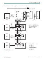
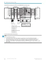
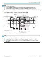
Wire switching inputs “Ext. input 1 and 2” of the CLV69x on the CDM420-0006 connection module
CLV69x
CDM420-0006
PNP sensor
U
V
GND
3.32 K
6.64 K
U
e
Out
GND
S6
e.g. photoelectric sensor
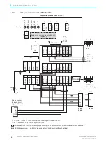
CMC600
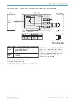
a) Sensor supplied by CDM420-0006
Serial Aux
(RS-232)
ON
OFF
S6 : SGND-GND
No
YES
S8 : CMC
17 SGND
8 Shield
39 +24 V*
X
Name
+24 V*
The CMC600 automatically transmits the
output states of its physical “Aux In 1 and
2” inputs to the serial Aux interface of the
CLV69x via the connecting cable using
software.
The CLV69x translates the statuses to its
logical “External input 1 and 2“ inputs.
“External
input 1,
input 2”
Characteristic data of switching inputs “Ext. input 1 and 2”
Current at the input starts the assigned
function, e.g. start reading cycle. (CLV69x
default settings: logic active high, deboun-
cing 10 mm)
– Opto-decoupled, reverse polarity protected
– Can be wired with PNP output of a sensor
– SensGND is the common insulated
reference potential for all switching inputs
Low:
U
e
≤ 2 V; I
e
≤ 0.3 mA
High:
6 V ≤ U
e
≤ 30 V;
0.7 mA ≤ I
e
≤ 5 mA
Switching
behavior
Properties
Electrical
values
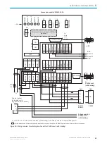
a) Switch supplied by CDM420-0006
CDM420-0006
U
e
GND
S6
CMC600
ON
OFF
S6 : SGND
No
YES
S8 : CMC
17 SGND
8 Shield
39 +24 V*
18 Aux In 1
+24 V*
SensGND
CDM420-0006
PNP sensor
U
V
GND
Out
GND
S6
e.g. photoelectric
sensor
U
V ext
U
e
CMC600
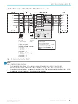
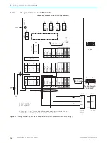
b) Sensor connected volt-free and externally supplied
No
YES
S8 : CMC
ON
OFF
S6 : SGND
17 SGND
8 Shield
39 +24 V*
18 Aux In 1
+24 V*
SensGND
SensGND
d) Switch connected volt-free
and externally supplied
Connection of the switch as under b)
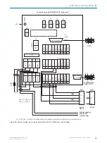
Functional assignment for switching inputs
via SOPAS-ET configuration software
CDM420-0006
Terminal X
18
19
Name
Aux In 1
Aux In 2
Switch S6 : SGND
ON: connect GND of the switching inputs with
the GND of the CDM420-0006/CMC600.
OFF: sensors connected volt-free to the switching
inputs of the CDM420-0006/CMC600.
Reference potential valid for all “Sensor 1 and 2”
switching inputs and optionally “AUX In 1 and 2”.
Figure 64: Wiring switching inputs “External input 1 and 2”
ELECTRICAL INSTALLATION
6
8014396/ZMG8/2017-07-04 | SICK
O P E R A T I N G I N S T R U C T I O N S | CLV69x
71
Subject to change without notice


