Devices with heating
User-supplied brackets
The brackets should meet the following requirements:
■
Stable mounting device
–
Alignment of the device in the x and y axes can be adjusted.
–
The mounting device must be able to bear the weight of the device and con‐
necting cables without shock.
■
Two M6 screws for mounting the device
–
The screw length depends on the wall thickness of the mounting device.
–
The maximum screw in depth in the device is 7 mm from the housing sur‐
face.
Addition for heated device variants
The scope of delivery for the heated devices includes an attachment kit for the thermal
decoupled mounting.
When preparing for mounting, the plastic plate of the attachment kit must be mounted
between the bracket and the device housing.
NOTE
The supplied counter-sunk screws replace the screws from mounting kit 1.
The supplied cylinder head screws replace the screws from mounting kit 2 or 3.
5.4
Mounting location
When selecting the mounting location, the following factors are significant:
b
Basic allocation of the scan line to the bar code
b
Reading distance to the bar code and aperture angle α
b
Angle alignment of the device
b
Avoidance of surface reflections
b
Count direction of the reading angle (position of the bar code along the scan line)
5.4.1
Basic allocation of the scan line to the bar code
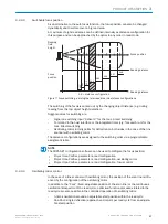
The basic allocation of the scan line to the bar code on the object depends on the ver‐
sion of the device (line scanner or line scanner with oscillating mirror).
CLV69x
Reading distance
Reading range
Figure 12: Allocation of the scan line to the bar code and conveyor direction
Line scanner
15°
15°
105°
Line scanner with oscillating mirror
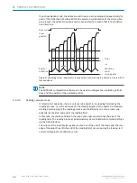
Figure 13: Line scanner (top view) and line scanner with oscillating mirror (side view)
MOUNTING
5
8014396/ZMG8/2017-07-04 | SICK
O P E R A T I N G I N S T R U C T I O N S | CLV69x
23
Subject to change without notice


