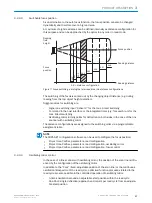
In each oscillation mode, the deflection width can be set (amplitude) independently for
each of the deflection directions. Within the selected cycle duration of the entire vibra‐
tion process, the deflection speeds can be set in relation to each other for both deflec‐
tion directions.
Read cycle
Focus
position
Angle of
deflection
‒φmax
+φmax
Timer
- or -
Oscillating
mirror
turning points
t
t
t1
t2
t3
t4
t5
t1
t2
t3
t4
t5
t6
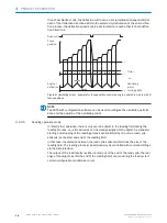
Figure 8: Oscillating mirror - example for focus position control during the search run, here with 6
focus positions
NOTE
The SOPAS-ET configuration software can be used to configure the oscillation perform‐
ance and the position of the oscillating mirror.
3.2.3.5
Reading operation mode
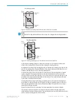
In “start/stop” operation, there is only ever one object in the reading field during the
reading process, i.e., all read codes can be clearly assigned to the object. As standard,
starting and stopping of the reading process are controlled by one or two read cycle
sensor(s) at the start and end of the reading field.
In this case, the distance between the read cycle sensors determines the size of the
reading field. The reading process can alternatively be controlled with command strings
via the data interface.
The output of the read results is either carried out at the end of the read cycle (the rear
edge of the object has left the end of the reading field) or even during the read cycle if
certain configurable conditions are met.
3
PRODUCT DESCRIPTION
18
O P E R A T I N G I N S T R U C T I O N S | CLV69x
8014396/ZMG8/2017-07-04 | SICK
Subject to change without notice


