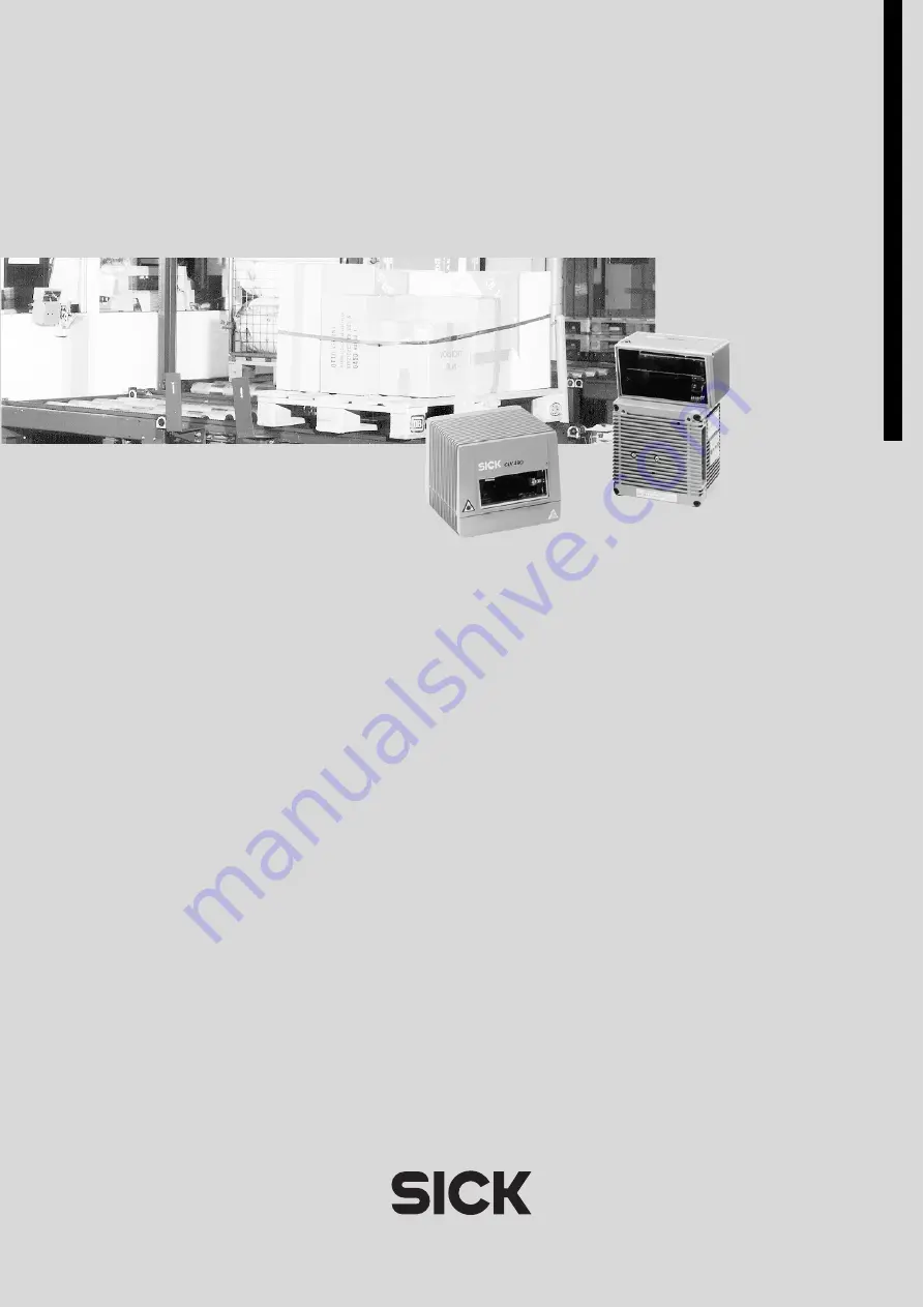
C L V 4 9 0
B a r C o d e S c a n n e r
A d v a n c e d l i n e
O
PE
R
A
TIN
G
I
NST
UCTIO
NS
Page 1: ...C L V 4 9 0 B a r C o d e S c a n n e r A d v a n c e d l i n e O P E R A T I N G I N S T R U C T I O N S ...
Page 2: ...a registered trademark of the Netscape Communications Cooper ation USA I ViewProTM is a registered trademark of EnReach Technology Inc USA Software Tool Function Version CLV 490 0010 0011 Firmware From V 0 90 0000 CLV 490 1010 1011 Firmware From V 0 90 0000 CLV 490 6010 6011 Firmware From V 1 22 K609 CLV 490 7010 7011 Firmware From V 1 22 K609 CLV 490 2010 2011 Firmware From V 1 30 KA54 CLV 490 30...
Page 3: ...ts functions Chapter 3 Product description Page 3 1 Chapter 6 2 Default settings Page 6 1 Chapter 6 5 Operating modes and outputing the reading result Page 6 19 Chapter 9 Technical data Page 9 1 Chapter 10 3 Installing and operating the external parameter memory Page 10 34 Starting the device with the default settings Chapter 6 3 Quick start Page 6 3 Installing the CLV Setup program Chapter 10 6 I...
Page 4: ... WindowsTM minimum requirement Windows 95TM 9 Install the CLV Setup software online CLV Setup Help and if necessary the I ViewProTM HTML browser from the CD on your PC 10 Connect the PC to the terminal interface of the CLV To do so connect the RS 232 data connection cable e g no 2 014 054 to the Service plug in the AMV S 60 11 Start the CLV Setup program CLV Setup establishes communication with th...
Page 5: ... Variants 3 1 3 1 3 System requirements 3 2 3 1 4 Design 3 4 3 2 Method of operation 3 5 3 2 1 Autofocus function 3 6 3 2 2 Event controlled dynamic focus control 3 7 3 2 3 Scan procedure variants 3 7 3 2 4 Additional components 3 8 3 3 Indicators and control elements 3 8 3 3 1 Control elements 3 8 3 3 2 Function of the LEDs 3 8 4 Installation 4 1 4 1 Installation sequence 4 1 4 2 Preparations 4 1...
Page 6: ...ge 5 13 5 5 4 Connecting the host interface 5 14 5 5 5 Connecting the CAN interface 5 15 5 5 6 Connecting the PC 5 15 5 5 7 Connecting the switching inputs 5 16 5 5 8 Connecting the Result 1 Result 4 switching outputs 5 19 6 Operation 6 1 6 1 Overview of steps for starting up the CLV 6 1 6 2 Default settings 6 1 6 2 1 Default settings of the line scanner CLV 490 all variants 6 2 6 2 2 Default sett...
Page 7: ... in Reading mode oscillating mirror errors 8 15 8 6 SICK Support 8 15 9 Technical data 9 1 9 1 Data sheet CLV 490 0010 2010 6010 bar code scanner 9 1 9 2 Data sheet CLV 490 1010 3010 7010 bar code scanner 9 2 9 3 Data sheet CLV 490 0011 2011 6011 bar code scanner 9 2 9 4 Data sheet CLV 490 1011 3011 7011 bar code scanner 9 3 9 5 Dimensioned drawings CLV 9 3 9 5 1 Line scanner standard device witho...
Page 8: ...0 8 1 Calculating the number of scans for standard decoders 10 51 10 8 2 Calculating the start position and mirror speed for the forward and return phase of the One Shot function 10 53 10 8 3 Calculating the necessary bar code distance if several bar codes are read on each object 10 54 10 9 Tables 10 55 10 9 1 Calculating the code length of a bar code 10 55 10 10 Discussion of a parameterization e...
Page 9: ...ries and plug cover 10 73 10 13 5 Plug in connections 10 74 10 13 6 Reading pulse generators 10 74 10 13 7 Network controller 10 74 10 14 Dimensioned drawings of the accessories 10 75 10 14 1 Angle bracket single no 2 013 824 10 75 10 14 2 Articulated bracket No 2 018 435 10 75 10 14 3 Quick clamping device No 2 016 110 10 75 10 15 Supplementary documentation 10 76 10 16 Glossary 10 77 10 17 Copy ...
Page 10: ... 1 Table 5 2 Cables for connecting the CLV 5 2 Table 5 3 Pin assignment of the 15 pin D Sub HD Host Term plug 5 6 Table 5 4 Pin assignment of the 15 pin D Sub HD I O socket 5 6 Table 5 5 Pin assignment of the 15 pin D Sub HD Host Term cable plug 5 7 Table 5 6 Pin assignment of the 15 pin D Sub HD I O cable socket 5 7 Table 5 7 Maximum cable lengths between the CLV and host 5 8 Table 5 8 Power cons...
Page 11: ... Troubleshooting result output errors in Reading mode 8 12 Table 8 8 Troubleshooting errors in the result status output in Reading mode 8 14 Table 8 9 Troubleshooting oscillating mirror errors in Reading mode 8 15 Table 9 1 Technical specifications of the CLV 490 0010 2010 6010 9 1 Table 9 2 Technical specifications of the CLV 490 1010 3010 7010 9 2 Table 9 3 Technical specifications of the CLV 49...
Page 12: ...1 Result 4 switching outputs 5 20 Fig 6 1 Bar code pattern Code 39 module width 0 35 mm Print ratio 2 1 6 3 Fig 6 2 Narrowing the visible range using limit values 6 10 Fig 6 3 Oscillating mirror Oscillating with fixed amplitude mode 6 13 Fig 6 4 Oscillating mirror Oscillating with variable amplitude mode 6 14 Fig 6 5 One Shot Object tracking bar code read from front 6 15 Fig 6 6 CLV Setup Displayi...
Page 13: ...CLV 490 1010 1011 Scanning frequency as a function of the reading distance and resolution 10 14 Fig 10 13 CLV 490 1010 1011 Standard density deflection range as a function of reading distance deflection angle and resolution 10 15 Fig 10 14 CLV 490 2010 2011 High density Reading field height as a function of the reading distance and resolution 10 16 Fig 10 15 CLV 490 2010 2011 High density Min and ...
Page 14: ... number of scans for fence type bar code arrangements 10 51 Fig 10 41 Line scanner with oscillating mirror calculating the number of scans for fence type bar code positioning 10 52 Fig 10 42 One Shot Line scanner with oscillating mirror calculating the number of scans for fence type bar code positioning 10 53 Fig 10 43 Required distance between the bar codes on an object 10 54 Fig 10 44 Parameteri...
Page 15: ...m high density CLV 490 3011 resolution from 0 20 mm high density with heater CLV 490 1010 resolution from 0 30 mm standard density CLV 490 1011 resolution from 0 30 mm standard density with heater CLV 490 7010 resolution from 0 40 mm low density CLV 490 7011 resolution from 0 40 mm low density with heater This document provides information on Mounting and connecting the device Startup Operating an...
Page 16: ... it quickly Warning Warnings are provided to prevent injury to operating personal or serious damage to the bar code scanners Always read warnings carefully and observe them at all times Note Indicates special features or characteristics Explanation Explanations provide background information on technical features Recommendation Recommendations help you carry out certain procedures more effectively...
Page 17: ...eyor belt Knowledge of the hardware and software environment of the relevant application e g conveyor belt Basic understanding of Windows 95TM 98TM Windows NTTM or Windows XPTM Ability to use an HTML browser e g Netscape NavigatorTM Basic understanding of data transfer methods Basic understanding of bar code technology 2 2 Intended use The CLV is designed to detect and decode bar codes automatical...
Page 18: ...aser specifications DIN EN 60825 1 latest version Laser power The laser operates at a wave length of λ 650 nm visible red light The power output at the reading window is max 2 8 mW The emitted radiation is not dangerous to human skin Laser warnings The laser warning symbols applicable for Europe Fig 2 1 can be found on the CLV at the following locations The laser warning symbol on line scanners is...
Page 19: ...minutes default setting However it does not end the reading interval In this case the CLV outputs the message Laser safety timeout on the terminal interface The reading interval must be terminated by resetting the trigger signal The laser diode is activated again by the next reading trigger In the Percentage Evaluation mode Adjusting mode and Show CP limits as well as in the Free running Reading m...
Page 20: ...s a typical power consumption of 9 W and max 18 W The line scanner equipped with an integrated heater has a typical power consumption of 75 W and max 90 W The line scanner with oscillating mirror equipped with an integrated heater has a typical power consumption of 75 W and max 100 W The values are given for devices with disconnected switching outputs 2 5 2 Disposal after removal from service Alwa...
Page 21: ...nnectors as well as sensors for generating the reading pulse 3 1 2 Variants The CLV is currently available in the following variants Table 3 1 CLV variants Type red light Part no Scanning method Resolution Reading window Heater High density CLV 490 2010 1 019 311 Line scanner From 0 2 mm End No CLV 490 3010 1 019 313 Line scanner with oscillating mirror From 0 2 mm Side No CLV 490 2011 1 019 312 L...
Page 22: ... DC to IEC 742 min 20 W AMV 30 071 18 30 V DC to IEC 742 min 40 W AMV 100 011 18 30 V DC to IEC 742 min 20 W AMV 200 011 18 30 V DC to IEC 742 min 40 W AMS 60 013 230 V AC 10 50 Hz AMS 60 012 115 V AC 10 50 60 Hz 3 Fitting cables see Chapter 5 2 2 Prefabricated cables overview Page 5 2 4 With external clock pulse supply via the Sensor switching input a suitable reading pul se sensor for signaling ...
Page 23: ...one CLV AMV 100 011 no 6 021 105 for 24 V DC max IP 65 For connecting two CLVs AMV 200 011 no 6 021 106 for 24 V DC max IP 65 or Alternatively a non SICK Power pack with a voltage output of 24 V DC 20 10 to IEC 742 functional extra low voltage and a minimum power output of 100 W Cable no 2 020 264 3 m with 15 pin D Sub HD connector and one open end for connecting the CLV to the non SICK Power pack...
Page 24: ... window Legend Drilled hole Ø 3 6 mm 6 mm deep Laser warning labels Blind hole thread M 6 7 mm deep for securing the device Blind hole thread M 4 10 mm deep for the connector cover Host Term connector 15 pin D Sub HD plug I O connector 15 pin D Sub HD socket LEDs status indicators Reading window Mark for count direction of the code position deflection direction of the laser beam Line scanner with ...
Page 25: ...ng pulse sensor Alternative trigger sources include Free running mode or a command via the host interface for more complex applications OTC trigger The current operating status is indicated by four LEDs If the trigger is supplied externally the Sensor switching input instructs the CLV to start the reading process The five IN 0 IN 4 switching inputs switch the focus position in response to certain ...
Page 26: ...by comparing it to the distance profile of the background Application with unobstructed view of the object restricted by other objects that protrude into the reading plane One object with barcode s only is inside the reading field during one reading pulse Differential background and tracking if several objects with different distances are positioned in the reading field at the same time distance c...
Page 27: ...measurement of the autofocus function can be additionally used to define the di stance configurations 3 2 3 Scan procedure variants Line scanner standard device Generates a scan line due to the V principle of the beam generation the reading field height the useful length of the scan line for evaluation purposes is dependent on the reading distance Line scanner with oscillating mirror The oscillati...
Page 28: ...nfigured via the terminal interface auxiliary interface using the CLV Setup program or using command strings sent via the host interface terminal inter face A variety of parameter options allow you to adapt the device to a wide range of appli cations The following can be defined The configuration of the code types The read evaluation and output properties The communication parameters of the host i...
Page 29: ...de is activated deactivated by reading pulse Lights up constantly in Free running mode since laser diode is always active Read Result Green LED is linked to the Result 2 switching output and indicates the selected result status for the defined pulse duration of the output Lights up after a successful read default Good Read Lights up if the match code comparison is active the bar code read matches ...
Page 30: ...nal memory and has reset the start option to START WITH EXTERNAL PARAMETERS CLV has loaded the internal parameter set Blinks constantly together with the Read Result LED2 The external parameter memory is either not connected or corrupt or the parameter set is too large to be copied CLV has loaded the internal parameter set Read Result Green Start option START WITH EXTERNAL PARAMETERS default Blink...
Page 31: ...tive evaluation Read Result Green Behavior dependent on the reading quality Extinguishes if reading rate 30 Blinks twice a second if reading rate 30 70 Blinks five times a second if reading rate 70 90 Lights up constantly if reading rate 90 Adjusting mode Sensor Green Lights up constantly since Free running mode is active Show CP limits Sensor Green Blinks bright dark alternately in the frequency ...
Page 32: ...Chapter 3 Operating Instructions CLV 490 Bar Code Scanner 3 12 SICK AG Division Auto Ident Germany All rights reserved 8 008 796 0000 25 06 2002 Product description Notes ...
Page 33: ...ith securing material for the CLV or Alternatively if the bracket is supplied by the user Stable mounting device that allows the alignment of the CLV to be varied in the x and y axes The weight of the CLV line scanner is 1 5 kg and 2 2 kg as a line scanner with oscillating mirror 2 screws M 6 for the CLV The screw length depends on the wall thickness of the bracket used Depth of engagement in CLV ...
Page 34: ... physical configuration of the host interface and the data transfer rate see Table 5 7 Page 5 8 Distance between the CLV and the AMV S 60 Connection Module The AMV S 60 Connection Module should not be located further than 10 m from the CLV since the CLV Setup program on the PC accesses the terminal interface RS 232 of the CLV via this module Fig 4 1 Line scanner replacing the laser warning labels ...
Page 35: ...variety of mounting positions and alignments in two planes Fig 4 3 shows two mounting examples The elongated holes in the mounting bracket no 2 013 824 and in the articulated bracket no 2 018 435 allow the CLV to be adjusted with a freedom of rotation of 15 The dimensions of the mounting brackets are shown in Chapter 10 14 Dimensioned draw ings of the accessories Page 10 75 Fig 4 2 Line scanner po...
Page 36: ...field is shown as a function of the reading distance for various resolutions module widths depending on the CLV type in Chapter 10 2 Specification diagrams Page 10 1 Fig 4 5 shows the definition of the reading distance a from the reading window and of the aperture angle α each of the two scanning methods The useful aperture angle is typically 56 for the line scanner and max 50 for the line scan ne...
Page 37: ...to the vertical axis Fig 4 7 In the case of the line scanner with oscillating mirror the laser beam is emitted at an angle of 105 with respect to the housing as it passes through the neutral position CW 50 whi le oscillating The device can only be flush mounted with the conveyor belt with limited de flection ranges Otherwise the device must also be mounted at an angle of 15 to ensure that the defl...
Page 38: ...ount direction of the code position and code angle In the case of the line scanner the count direction of the code position is marked by a small triangle above the reading window By determining this data the device can separate identical bar codes code type code length and data content identical and assign the bar code data in the reading result to its position on the object Tip In the default set...
Page 39: ...equired ac cessories Page 4 1 2 Place the object containing the bar code within the reading field of the CLV in the posi tion at which it is to be read with the conveyor belt switched off 3 Align the CLV with the bar code in accordance with the scanning method in such a way that with the line scanner the back of the device with the LEDs is almost parallel with the bar code surface with the line sc...
Page 40: ... 15 3 Start Windows and the CLV Setup program see Chapter 10 6 3 Starting CLV Setup Page 10 43 Choosing the standard decoder 4 Choose the CODE CONFIGURATION tab 5 Click the STANDARD option in the DECODER section 6 Download the settings to the CLV by clicking on the toolbar The DOWNLOAD PARAMETERS dialog box is then displayed 7 Confirm the dialog box by choosing TEMPORARY The CLV then operates with...
Page 41: ...0 100 With event controlled dynamic focus control for each defined reading range distance configuration check the selected focus position and correct the parameter settings if necessary see Chapter 6 4 4 Guide to parameterization menu Page 6 8 16 Tighten the screws on the CLV The CLV is aligned with the bar code 4 3 3 Adjusting mode The Adjusting mode helps you to position the center of the scan l...
Page 42: ...the CLV is accessed via the internal Service plug Detailed information on the mounting and electrical installation procedures is provided in the Operating Instructions for the AMV S 60 Connection Module order no 8 008 296 4 4 2 Mounting the external reading pulse sensor If the CLV is triggered by an external reading pulse sensor the sensor must be mounted in the vicinity of the CLV The Sensor swit...
Page 43: ...s launched The CLV is in Reading mode default SMART decoder Monitor the reading result during each of the subsequent steps Line scanner with oscillating mirror In default setting the CLV deflects the scan line default setting about the fixed position CW 50 with a frequency of 1 Hz at a max angle of 20 40 CW 50 CW corresponds to an angle of emergence of 105 7 Move objects with bar codes into the CL...
Page 44: ...ranges 2 Mount distance sensors e g photoelectric reflex switches one above the other in a row at the mounting location to measure the object distance see also assignment Table 5 20 Page 5 18 It is advisable to mount these distance sensors opposite the direction of motion of the conveyor belt at approx 100 mm in front of the reading pulse sensor 3 Connect the distance sensors to the IN 0 IN 4 swit...
Page 45: ...aximum of 8 distance ranges synchronously to the reading process using command strings 4 5 Dismantling the device 1 Switch off the power supply to the AMV S 60 Connection Module 2 Undo the screws for the cable connections on the CLV and disconnect the cables With mounted external parameter memory optional Undo both screws and remove the cover 3 Unscrew the CLV from the mounting device When removin...
Page 46: ...Chapter 4 Operating Instructions CLV 490 Bar Code Scanner 4 14 SICK AG Division Auto Ident Germany All rights reserved 8 008 796 0000 25 06 2002 Installation Notes ...
Page 47: ...4 V DC Enclosure rating IP 30 max IP 54 5 2 3 AMV 100 Connecting one CLV Operating voltage 18 30 V DC Enclosure rating IP 52 with connector cover max IP 65 5 2 3 BMV BMH 10 Bus Connection Module Connecting one CLV to the Profibus DP DeviceNet or Ethernet Operating voltage 20 30 V DC Enclosure rating IP 52 with connector cover max IP 65 5 2 4 BMS 20 Interbus S Connecting one CLV to the Interbus S O...
Page 48: ... Optional cables Length Type CLV without heater 0 40 C AMV S 60 2 x No 2 020 302 or 1 x No 2 020 307 3 m 3 m Connecting cable plug socket Ext parameter memory with 2 cables plug socket BMV BMH 10 Bus Connection Module 1 x No 2 020 307 or 1 x No 2 021 298 3 m 3 m Ext parameter memory with 2 cables plug socket Connector cover to connector cover AMV 30 071 2 x No 2 020 302 or 1 x No 2 020 307 3 m 3 m...
Page 49: ...5 4 a CLV without heater Connection modules AMV S 60 and AMV 30 071 The cables no 2 020 302 can be extended to 10 m terminal interface RS 232 b CLV with heater Connection modules AMV 100 and AMV 200 The cables no 2 020 302 must not be extended If longer cables are required the entire power supply system Pin 1 Pin 5 must be connected with a wire cross section of at least 0 75 mm2 with a maximum len...
Page 50: ...longer cables are required the entire power supply system Pin 1 Pin 5 must be connected with a wire cross section of at least 0 75 mm2 at a maximum of 10 m Recommendation Use the cable no 2 021 298 with two connector covers length 3 m The BMS 20 is not suitable for powering CLVs with heater The procedures for connecting and configuring the Bus Connection Modules are described in the following docu...
Page 51: ...Connection Module AMV 100 200 AMV 100 Cover the terminals on the CLV with the connector cover parameter memory no 2 021 689 labeled SCANNER Connect the other connector covers labeled HOST to the corresponding connections on the AMV 100 AMV 200 see AMV 100 proceed in the same way with the second CLV 5 2 6 Connections cables for the IP 65 connector cover connection to AMV 100 200 or BMV 10 The conne...
Page 52: ...4 Bus R_485 15 CAN L CAN Bus IN OUT Housing Shield 1 Pin 1 is jumpered with Pin 1 of the I O connection in the CLV Table 5 3 Pin assignment of the 15 pin D Sub HD Host Term plug 1 10 15 6 11 5 Pin Signal Function 11 VS Supply voltage 2 IN 1 Switching input trigger for focus control 3 Sensor Switching input external reading pulse 4 Result 1 Switching output variable function 5 GND Ground 6 IN 0 Swi...
Page 53: ...Bus RT_485 13 Bus R_485 14 Bus R_485 15 CAN L CAN bus IN OUT Housing Shield 1 Pin 1 is jumpered with Pin 1 of the I O connection in the CLV Table 5 5 Pin assignment of the 15 pin D Sub HD Host Term cable plug 1 10 15 6 11 5 Pin Signal Function 11 VS Supply voltage 2 IN 1 Switching input trigger for focus control 3 Sensor Switching input external reading pulse 4 Result 1 Switching output variable f...
Page 54: ...e 5 9 contains a list of the available intervals Tip The device number can be selected on the DEVICE CONFIGURATION tab in the CLV Setup program Interface type Transfer rate Distance from host RS 232 Up to 19 200 bit s 38 400 57 600 bit s Max 10 m Max 3 m RS 422 4851 Max 38 400 bit s Max 57 600 bit s Max 1 200 m Max 500 m 1 with suitable line termination Table 5 7 Maximum cable lengths between the ...
Page 55: ...for the power supply Pin 1 Pin 5 should be at least 0 15 mm2 or 0 75 mm2 for CLVs with heater with a max length of 10 m a Connecting the CLV without a connector cover external parameter memory The two cables no 2 020 303 and no 2 020 264 with open cable end on one side are required to connect the CLV The wire color assignments are shown in Table 5 10 and Table 5 11 Page 5 10 The cables must not be...
Page 56: ...ctor cover pa rameter memory no 2 020 981 Connect the free cable ends accordingly The wire color assignments are shown in Table 5 12 and Table 5 13 CLV with heater Available on request Pin Signal Wire color 11 VS Red 2 IN 1 White 3 Sensor Brown 4 Result 1 Violet 5 GND Blue 6 IN 0 Green 7 IN 2 Yellow 8 Result 2 Grey 9 INGND Black 10 Result 3 Grey pink 11 IN 3 Red blue 12 IN 4 White green 13 I2C SDA...
Page 57: ...9 TD RS 422 485 Host TxD RS 232 Host Black 10 CAN H Grey pink 11 Bus RT_485 Red blue 12 Bus RT_485 White green 13 Bus R_485 Brown green 14 Bus R_485 White yellow 15 CAN L Yellow brown Shield Orange 1 Pin 1 is jumpered with Pin 1 of the I O connection in the CLV Table 5 12 Wire color assignment of cable 1 for external parameter memory no 2 020 981 Pin Signal Wire color 1 1 VS Red and pink 2 IN 1 Wh...
Page 58: ...r and open cable end Cable 2 data and function interfaces 15 pin D Sub HD socket plug in the connector cover and open cable end Pin Connector cover Signal Wire color 1 Socket VS Red 5 Socket GND Black Table 5 14 Wire color assignment cable 1 for connector cover no 2 021 267 Pin Connector cover Signal Wire color 2 Plug IN 1 White 3 Plug Sensor Brown 4 Plug Result 1 Green 6 Plug IN 0 Yellow 7 Plug I...
Page 59: ...r memory 1 Mount the connector cover with the external parameter memory no 2 020 307 on the Host Term and I O connections of the CLV and screw it tightly into position 2 Connect the two free plug connections on the cables to the corresponding connections on the Connection Module and secure them tightly The data and function interfaces of the CLV are connected to the Connection Module b Power suppl...
Page 60: ...es EMC require ments Ensure that the maximum cable lengths are not exceeded see Table 5 7 Page 5 8 Recommendation 2 Apply the shield on one side Default In the default setting the CLV communicates with the host via the host interface using the values shown in Table 5 16 Fig 5 2 Connecting the host interface AMV 60 011 AMS 60 012 013 RS 232 RS 422 9 pin D Sub connector at PC RS 485 Connection diagr...
Page 61: ... values under DATA FORMAT and INTERFACE PROTOCOL 5 5 5 Connecting the CAN interface Instructions for the connection and for configuration of the CLV to use the device in the SICK specific CAN Scanner Network or in a CANopen network see the Operating Instruc tions Application of the CAN interface no 8 009 180 English edition 5 5 6 Connecting the PC The CLV is operated and configured with the PC bas...
Page 62: ...ulse sensor as shown in Fig 5 4 Tip You can change the switching mode polarity debouncing response for first pulse after po wer up of the SENSOR switching input on the DEVICE CONFIGURATION tab in the CLV Setup program Click the EDIT READING TRIGGER button Enter the values in the dialog box displayed For connecting the host interface via the AMV S 60 Connection Module see the Operating Instructions...
Page 63: ...namic focus control Fig 5 5 shows the connections for the IN 0 IN 4 switching inputs Table 5 18 shows the pin assignment on the CLV and the terminal assignment in the AMV S 60 Table 5 19 Page 5 18 contains the characteristic data for these inputs Table 5 20 Page 5 18 shows the input combinations based on the distance configurations The interaction of the swit ching input functions is shown in Tabl...
Page 64: ...oelectric switches bright switching 0 0 0 0 0 N 1 DC 1 DC 6 0 0 0 0 1 N 2 DC 2 DC 5 0 0 0 1 0 N 3 DC 3 DC 4 0 0 0 1 1 N 4 DC 4 DC 4 0 0 1 0 0 N 5 DC 5 DC 3 0 0 1 0 1 N 6 DC 6 DC 3 0 0 1 1 0 N 7 DC 7 DC 3 0 0 1 1 1 N 8 DC 8 DC 3 0 1 0 0 0 N 9 DC 8 DC 2 0 1 0 0 1 N 10 DC 8 DC 2 0 1 0 1 0 N 11 DC 8 DC 2 0 1 0 1 1 N 12 DC 8 DC 2 0 1 1 0 0 N 13 DC 8 DC 2 0 1 1 0 1 N 14 DC 8 DC 2 0 1 1 1 0 N 15 DC 8 DC ...
Page 65: ...ood Read 100 ms Fig 5 6 Page 5 20 shows the connections for the Result 1 Result 4 switching outputs Table 5 22 Page 5 20 shows the pin assignment on the CLV and the terminal assignment in the AMV S 60 Table 5 23 Page 5 20 contains the characteristic data for these outputs The four outputs have the same characteristic data Parameter settings of switching inputs Effects IN 3 IN 4 Focus control1 Focu...
Page 66: ...ult 4 switching outputs VS 18 30 V DC for CLV without heater 24 V DC 20 10 for CLV with heater Pin and terminal assignment for Result X see Table 5 22 Pulse duration depending on setting 10 ms 900 ms 100 ms 9 900 ms 00 static to the end of next reading pulse GND Result X Fuse Result X Y GND RL VS 5 Logic Temperature sensor AMV 60 011 AMS 60 012 013 Terminal assignment Z T 35 Output Result X CLV I ...
Page 67: ...h the default settings this is however not the case the first time the CLV with external parameter memory is switched on The default settings are stored permanently both in the ROM of the CLV and in the CLV Setup database They can be loaded to the RAM of the CLV at any time and displayed in the tabs of the CLV Setup program Displaying and printing out a complete set of default settings in CLV Setu...
Page 68: ...high debouncing 20 30 ms Switching outputs Not inverted pulse duration 100 ms Status output function Result 1 Device Ready static Result 2 Good Read Result 3 No Read Result 4 Match 1 CLV arrangement Stand alone Read result output Host interface Device number 1 Start option Load the parameter set of the external parameter memory Host interface type RS 422 485 Protocol NAK start character STX stop c...
Page 69: ...ation In this case proceed as described in Chapter 6 3 2 Switching the CLV with external pa rameter memory connected on for the first time with the factory default settings Page 6 4 Line scanner with oscillating mirror In the default setting the CLV deflects the scan line around the position CW 50 with a frequency of 1 Hz and an oscillating amplitude of 20 40 CW 50 CW correspond to a deflection an...
Page 70: ...Page 5 15 5 Start Windows and the CLV Setup program see Chapter 10 6 3 Starting CLV Setup Page 10 43 CLV Setup attempts by default to communicate with the CLV via COM 1 If the communi cation parameters match CLV Setup uploads the current parameter set from the RAM of the CLV to the internal database and displays the values in the tabs the para meter set contains the factory default settings when t...
Page 71: ...nd for starting and operating the user interface are described in the Appendix Chapter 10 6 Installing and operating the CLV Setup program Page 10 41 Transferring a parameter set between CLV Setup and the CLV When the CLV is being parameterized CLV Setup runs in the offline mode To be able to modify the current parameter set of the CLV this first has to be loaded to CLV Setup from the CLV This pro...
Page 72: ...hoose the COPY NOW INTERNAL PARAMETER SET TO EXTERNAL MEMORY option CLV Setup then instructs the CLV to copy the new parameter set to the external memory The Device Ready LED lights up again The internal and external parameter sets are now identical See also Chapter 10 3 5 Adjusting the parameter set in the external parameter memory af ter it has been downloaded to the CLV Page 10 36 Saving a para...
Page 73: ...ines for individual code types Number of identical reads multiple reads Minimum and maximum number of bar codes to be read output Kind of Start Stop recognition Activation of the comparison of the code position for the separation of identical bar co des Recommendation To enhance the reading reliability with fast applications only activate those code types and code lengths that are actually relevan...
Page 74: ...eters that were not recognized by CLV Setup after an upload Note CLV Setup Online Help contains a detailed description of the functions of the parameters and their valid entries see Chapter 10 6 6 CLV Setup Help Page 10 46 for calling up Help 6 4 3 Parameterizing example For a simple application Chapter 10 10 Discussion of a parameterization example Page 10 56 in the appendix shows an example of t...
Page 75: ...ing see Table 6 5 Page 6 10 AUTOFOCUS ÖMODE Minimum distance or Differential background or Differential background and tracking see Table 6 5 Page 6 10 3 Configure CLV for distance measurement define visible range AUTOFOCUS ÖEDIT READING FIELD Minimum Code Position CP Maximum Code Position CP AUTOFOCUS ÖEDIT READING FIELD Minimum Code Position CP Maximum Code Position CP Oscillating mirror amplitu...
Page 76: ...um Distance Differential background Differential background and Tracking Condition 1 object in reading field per reading interval 1 object in reading field per reading interval No of objects in the reading field per reading interval 1 1 Limits autofocus limitation 2 Limits Scan angle limitation 3 Limits oscillation angle limitation1 4 Limits autofocus space 5 Edit scanner position angles angle alp...
Page 77: ...rema 2 Choose focus switchover point referred to reading pulse FOCUS TRIGGER SOURCE ÖInputs Serial Autofocus Immediate or Synchronous Latched FOCUS TRIGGER SOURCE ÖInputs Serial Autofocus Immediate or Synchronous Latched 3 Set up focus control DISTANCE CONFIGURATION ASSIGNMENT TABLE ÖDistance Configuration Focus Position Minimum Code Position CP Maximum Code Position CP ÖAssignment Table Index Val...
Page 78: ... respectively ÖDistance Configurations Oscillating Mirror Amplitude 3 Choose Fixed Position mode or ÖOSCILLATING MIRROR tab ÖOSCILLATING MIRROR Fixed Position ÖFIXED POSITION Stationary Position CW 4 Choose One Shot mode ÖOSCILLATING MIRROR tab ÖOSCILLATING MIRROR One Shot ÖONE SHOT ÖPHASE 1 Mirror Speed Start Position Distance Configuration no ÖPHASE 2 Mirror Speed Start Position DistanceConfigur...
Page 79: ...eflects the scan line up to the maximum angle of deflection of 40 CW corresponds to 20 Fig 6 3 illustrates this mode when a bar code is read from above 2 Oscillating with Variable Amplitude mode The deflection range can be parameterized separately for each of the maximum of 8 di stance configurations focus positions The minimum maximum values that can be set for the deflection range for fast appli...
Page 80: ...n be parameterized separately for each phase The end position of the one phase forms the start position of the other phase Fig 6 5 Page 6 15 illustrates this mode with object tracking During the forward phase the front of the object that moves towards the oscillating mirror is swept once by the scan line from top to bottom in accordance with the conveyor speed Multiple focus position switchovers a...
Page 81: ...G Division Auto Ident Germany All rights reserved 6 15 Operation Fig 6 5 One Shot Object tracking bar code read from front t1 t0 Conventionally required reading range Reduced reading range through One Shot function Line scanner Line scanner with oscillating mirror Reading range Reading range ...
Page 82: ...dard or Fast ÖFIRST TRIGGER SENSOR Dynamic or Static 3 Trigger source Serial Interface choose trigger character ÖEDIT READING TRIGGER ÖSERIAL INTERFACE Standard Trigger or Single Character 4 Trigger source Free Running choose timeout ÖEDIT READING TRIGGER ÖEND OF LABLE FREE RUNNING Timeout 5 Reading trigger choose source for end ÖEDIT READING TRIGGER ÖEND OF READING INTERVAL Generated by Trigger S...
Page 83: ...ng result Ö DEVICE CONFIGURATION tab Ö Odette filter Sort reading result Ö DATA STRINGS tab Ö Output Sequence Sort Mask reading result ÖDATA STRINGS tab ÖFormat Mask Destination result data strings ÖHOST INTERFACE tab Ödestination of result data strings Host Interface Arrangement in data network Ö DEVICE CONFIGURATION tab Ö scanner arrangement Physical interface Ö HOST INTERFACE tab Ö Data Format ...
Page 84: ...rminator Ö DATA STRINGS tab Ö Output Format Position of separator in data output string Ö DATA STRINGS tab Ö Separator Position Set wrong read format ÖDATA STRINGS tab ÖWrong read format Character Count and Error String If necessary parameterize activate test string Ö DATA STRINGS tab Ö Test String Parameterize special functions ÖDATA STRINGS tab Ö Specials f Parameterizing the auxiliary interface...
Page 85: ...forms a self test after it has been switched on It switches to Reading mode Device Ready LED lights up In the default setting the Sensor switching input is the ex ternal trigger source of the reading pulse The reading result is output by the CLV at the end of the reading pulse via the host interface default setting and terminal interface The reading result of the terminal interface can be displaye...
Page 86: ... Also refer to Chapter 6 3 1 Swit ching the CLV on for the first time with the factory default settings Page 6 3 4 Ending the reading pulse The CLV displays the reading result in the output window of the Terminal Emulator The Read Result LED lights up for a duration of 100 ms default setting Fig 6 6 shows two examples of the output of a reading result Good Read and No Read The reading result compr...
Page 87: ...emporal mean value of the identification quality n Number of detected bar codes AK No of the used distance configuration1 2nd line 0123412345 Data contents of the bar code 3rd line C39 ID Code type Code 39 along _99 Identification quality ST Read status ST 0 Good Read CP Code position CL Code length number of characters CA Scan effort CS Code reliability CK Code continuity DI Decoding direction F ...
Page 88: ...8 Click the SW TRIGGER OFF button or press F8 CLV Setup sends a stop command to the CLV The Sensor LED is extinguished The CLV switches off the laser diode The CLV displays the reading result in the output win dow of the Terminal Emulator The Read Result LED lights up for a duration of 100 ms default setting 6 5 2 Percentage evaluation In the Percentage evaluation mode the quality of the reading f...
Page 89: ...olled focus control the distance configuration that corresponds to the reading distance of the object default setting no 1 focus position F1 1 200 mm 8 Confirm the dialog box with OK The Device Ready LED is extinguished The CLV initiates the percentage evaluation and outputs the reading results continuously 9 Present the bar code pattern from Fig 6 1 Page 6 3 and monitor the reading results in the...
Page 90: ...the Adjusting mode the CLV behaves in the following manner In Oscillating mode default setting oscillating with a fixed amplitude the CLV shuts of oscillation and positions the scan line under the angle CW 50 corresponds to an angle of deflection below 105 This position cannot be altered In One Shot mode the CLV positions the scan line under the angle CW 50 In Fixed Position mode the scan line s s...
Page 91: ...g with a fixed amplitude the CLV shuts off oscillation and positions the scan line under the angle CW 50 corresponds to an angle of deflection below 105 This position cannot be altered in One Shot mode the CLV positions the scan line under the angle CW 50 in Fixed Position mode the scan line s selected position remains unchanged 1 Mount the CLV at the reading station and align it with an object co...
Page 92: ... values defined for the active evaluation range of the scan line can be checked directly during parameteri zation The restricted active evaluation range shortens the evaluation time for fast applica tions for example because the evaluation routine only has to take account of unblanked parts of the scan line The range is restricted by entering appropriate values for MINIMUM CODE POSITION and MAXIMU...
Page 93: ...in the toolbar The Terminal Emulator window is then displayed The CLV is in the Reading mode 2 In the DEVICE MODE section choose SHOW CP LIMITS The dialog box for the distance configuration is then displayed 3 Click the distance configuration for which the active evaluation range of the scan line has been restricted DC specific The Device Ready LED is extinguished The CLV cancels the Reading mode ...
Page 94: ...ade The CLV then returns to the Reading mode and the Device Ready LED lights up 6 5 7 Reading diagnosis Function of the terminal interface In this mode the CLV outputs the data contents of all the bar codes that were read including those that according to the evaluation criteria were not read properly and were thus incorrect together with the associated reading diagnosis data via the terminal inte...
Page 95: ...nload to the CLV by clicking in the toolbar The DOWNLOAD PARAMETERS dialog box is then displayed 3 Choose the TEMPORARY storage option in the dialog box The terminal interface is then set to the MONITOR HOST INTERFACE function until the CLV is swit ched off again Displaying the data traffic of the host interface in the Terminal Emulator The data traffic of the host interface can be displayed in th...
Page 96: ...b Up to 10 elements consisting of constants and or reading diagnosis data can be entered in the header in the separator and in the terminator 1 Choose the DATA STRINGS tab 2 Click the HEADER field The EDIT PARAMETER TFH dialog box is then displayed 3 Click the desired constants or placeholders for the reading diagnosis data The selected elements appear in the text box at the top of the dialog box ...
Page 97: ...CLV checks that its hardware components are functioning correctly A final messa ge via the terminal interface provides information on the test result The CLV does not output a reading result during the test routine 1 Click in the toolbar The Terminal Emulator window is then displayed The CLV is in the Reading mode 2 In the DEVICE MODE section choose SELF TEST The Device Ready LED is extinguished T...
Page 98: ...ing functions are available Background teach in reset to default Percentage evaluation Show CP limits Adjustment mode Copy parameter memory Analyze scanner network Choose CLV 490 DEVICE FUNCTIONS and the desired function or press the F2 key The EXECUTE DEVICE FUNCTIONS dialog box is then displayed Choose the desired function in the EXECUTE menu in the menu CLV Setup starts the function and where a...
Page 99: ...ting mode The user is not required to carry out any further steps here Chapter 10 5 System messages Page 10 40 explains the contents of the messages 6 6 3 Warning messages Warning messages indicate that it was not possible to perform an action or that the values set for the parameters can cause an error while the bar code is being read Table 6 12 lists the warning messages in alphabetical order to...
Page 100: ...ch off the power supply of the AMV S 60 or unplug both of the CLV s connecting cables from the connection module The last parameter set stored permanently in the CLV remains valid We recommend that you print out the configuration file in order to archive the parameter set 1 Click in the toolbar The PRINT FILE dialog box is then displayed 2 Enter a comment in the input field in order to assign the ...
Page 101: ...mage your eyesight Never look directly into the path of the beam similar to sunlight Never look directly into the reading window while the device is in operation Switch off the device while it is being cleaned Damage on the reading window The reading window is made of glass Scratches and streaks on the window will reduce the reading performance Use a mild non scouring detergent Never use scratchin...
Page 102: ...displayed on the terminal interface The messages can be displayed on the screen in the extended mode of the Terminal Emulator in the CLV Setup program See Chapter 8 3 Error messages Page 8 2 7 3 Disposal Irreparable devices or devices that are no longer required must be disposed of in an environmentally friendly manner 1 Always observe the applicable national waste disposal regulations 2 Remove th...
Page 103: ...s out a self test in which it checks important hardware components before it is initialized parameter set loaded and device functions initialized The self test can be repeated at any time by cancelling Reading mode See Chapter 6 5 10 Self test Page 6 31 If the CLV detects an error during the self test or at any other time it outputs the error status ST 3 on the host interface Prerequisite the erro...
Page 104: ...verflow 201 215 DSP error If the error occurs again after the CLV is restarted contact the SICK Service department 1 Deactivate the CAN interface to suppress error numbers above 300 not relevant in stand alone mode To do so upload the parameter set from the CLV using CLV Setup choose the CAN INTERFACE tab and deactivate the function in the CAN INTERFACE FUNCTION section Download the parameter set ...
Page 105: ...ion at the host interface To do so upload from the CLV using the CLV Setup program choose the AUXILIARY INTERFACE tab and select MONITOR HOST INTERFACE from the drop down list Download to the CLV Start the Terminal Emulator Master slave trigger too soon The new reading pulse for the master is received before its timeout has elapsed Timeout for the master is too long Check the coordination between ...
Page 106: ...mber of slaves To do so upload from the CLV using the CLV Setup pro gram choose the DEVICE CONFI GURATION tab and check the NUMBER OF SLAVES in the SCAN NER ARRANGEMENT section Download any changes to the CLV As above but check the time out defined for the master Check the cables between the slaves Wrong parameters master slave After selection of the master slave function individual param eter val...
Page 107: ...LEDs blink conti nuously 2 Start option START WITH EX TERNAL PARAMETERS The CLV has not loaded the external parameter set In stead it has loaded the inter nal parameter set to its RAM The CLV however does not output data on the host interface External parameter memory empty External parameter memory not connected The parameter set in the exter nal memory is not from a CLV 490 External parameter me...
Page 108: ...d and 3rd paragraph contact the SICK Service department Contact the SICK Service department See 4 Remedy 4th paragraph 5 When the device is switched on the Device Ready LED and Read Result LEDs blink alternately for approx 10 s The Device Ready LED then lights up con stantly Start option START WITH COPY INTERN EXTERN The CLV has successfully copied the internal parameter set to the external memory...
Page 109: ...r 6 3 2 Switching the CLV with external parameter memory connected on for the first time with the factory default settings Page 6 4 3 error external parameter memory full internal parameters loaded Error type 108 Start option START WITH COPY INTERN EXTERN The CLV was not able to copy the internal parameter memory It has loaded the internal pa rameter set to its RAM The internal parameter set is to...
Page 110: ...ter memory is connected cor rectly free wiring check wire assignment Repeat the startup procedure If the error is still present contact the SICK Service department 7 warning additional unknown parameter s external parameters loaded Error type 101 114 Start option START WITH EXTER NAL PARAMETERS The CLV has successfully loaded the external parameter set with tolerated errors1 to its RAM Transfer ok...
Page 111: ...ameterized number of slaves does not match the actual number of slaves available The master timeout is too short The data connection between the slaves and or the master has been interrupted Check the entered number of slaves Check the master timeout setting Check the cables between the slaves and the master 7 The source of the reading result is the auxiliary input via the terminal interface The b...
Page 112: ...se default setting Device Ready After switching on the power supply The CLV has no power The CLV has diagnosed a device error during the self test During operation The CLV is not in Reading mode The CLV has deactivated the laser diode 10 min default setting after the start of the current reading pulse trigger mode sensor input serial interface Check wiring power connector fitted securely to the AM...
Page 113: ...functioning 2 Trigger mode Serial interface The CLV cannot be clocked the Sensor LED does not light up the scan line does not appear Incorrect reading pulse source para meterized on the CLV The CLV is not receiving any command strings to start the reading interval on the data interface In the CLV Setup program choose the DEVICE CONFIGURATION tab READING TRIG GER Mode section is serial interface se...
Page 114: ...e 8 11 Align CLV Is bar code at center of scan line Check the reading quality with the CLV Setup software Choose PERCEN TAGE EVALUATION See Chapter 6 5 2 Per centage evaluation Page 6 22 In the CLV Setup program choose the READING CONFIGURATION tab click the EDIT AUTOFOCUS respectively DISTANCE CONFI GURATION ASSIGMENT TABLE button Are the min and max code position values cor rect Check with SHOW ...
Page 115: ...FREE Download temporarily to CLV Start PERCENTAGE EVALUATION Code type and length are displayed in the reading result Enable recorded code type in the CODES section and disable all other types Enter the code length under FIXED on the code type tab Download to CLV Check sufficient blank zones present Print contrast adequate Specified print tolerances exceeded In the CLV Setup program choose REA DIN...
Page 116: ...IT CODES button Choose the tab for the rel evant code Is the TRANSMIT CHECK DIGIT checkbox activated Change if neces sary Download to CLV Malfunction Possible cause Remedy Table 8 7 Troubleshooting result output errors in Reading mode Malfunction Possible cause Remedy The Result 1 default setting Device Ready Result 2 default setting Good Read Result 3 default setting No Read Result 4 default sett...
Page 117: ...deflection 40 CW even though a variable amplitude e g 10 CW is set in the distance configuration 1 OSCILLATING WITH MAXIMUM AMPLITUDE set on the CLV by mistake The oscillating amplitude is paramterized in the wrong distance configuration here no 2 The distance configuration focus position was not changed From the OSCILLATING MIRROR tab choose OSCILLATING WITH VARIABLE AMPLITUDE Download to the CLV...
Page 118: ...Chapter 8 Operating Instructions CLV 490 Bar Code Scanner 8 16 SICK AG Division Auto Ident Germany All rights reserved 8 008 796 0000 25 06 2002 Troubleshooting Notes ...
Page 119: ...l bar codes per reading interval Print ratio 2 1 3 1 No of multiple reads 1 99 Optical indicators 4 x LEDs status indicators Reading pulse Sensor switching input Free running Serial interface OPC OTC Host data interface RS 232 or RS 422 485 variable data output format Data transmission rate 300 57 600 bit s Protocols SICK Standard SICK Network and 3 964 R Physical configurations Stand alone SICK N...
Page 120: ...enter position CW 50 Trigger source for focus control also oscillating mirror reversal points Useful aperture angle max 50 Oscillating mirror functions permanent variable position oscillating amplitude per DC variable or fixed One Shot1 Oscillating frequency 0 2 4 Hz Max angle of deflection max 20 40 CW set with software Reading ranges see Page 10 9 see Page 10 21 see Page 10 31 Deflection ranges ...
Page 121: ...mperature graph see Chapter 10 4 Optional heating Page 10 38 Power on delay 35 40 min at 24 V DC and min ambient operating temperature 35 C Operating voltage 24 V DC 20 10 Power consumption typically 75 W max 90 W Required cross section min 0 5 mm2 for power supply Weight approx 2 2 kg Ambient operating storage temperature 35 35 C 20 70 C Table 9 4 Technical specifications of the CLV 490 1011 3011...
Page 122: ...rror without with heater Fig 9 2 Dimensions of the CLV 490 line scanner with oscillating mirror side reading window 38 5 12 82 56 21 78 117 2 127 5 33 4 43 3 86 3 5 25 5 m a x 2 0 15 70 183 Device Ready Sensor Read Result Data CLV490 10 10 10 50 All values in mm Blind hole thread M 6 7 mm deep Drilled hole 3 6 6 mm deep CLV 490 1010 CLV 490 1011 CLV 490 3010 CLV 490 3011 CLV 490 7010 CLV 490 7011 ...
Page 123: ... for the PC based CLV Setup program Configuring a CLV using command strings Parameter value calculations for configuring the CLV Tables Discussion of a parameterization example Special applications and procedures Instructions for replacing a CLV copying the parameter set Accessories Dimensioned drawings of the accessories Notes on supplementary documentation Glossary Copy of the EC Declaration of ...
Page 124: ...iagrams for the line scanner CLV Type Resolution Scanning method Diagram Page CLV 490 1010 1011 Standard density L s with osci mirror Reading field height resolution as a function of reading distance 10 9 CLV 490 1010 1011 Standard density L s with osci mirror Min and max reading distance DOF for 0 35 mm 40 10 10 CLV 490 1010 1011 Standard density L s with osci mirror Min and max reading distance ...
Page 125: ...ight as a function of the reading distance and resolution Reading distance mm 700 600 500 400 400 600 800 1000 1200 1400 1600 1800 2000 2200 300 200 100 0 100 200 300 400 500 600 700 Line scanner front reading window Reading field height mm Reading conditions see Table 10 1 Page 10 1 Characteristics field scanning frequency reading distance see Fig 10 6 Page 10 8 Resolution 0 30 mm 0 35 mm 0 50 mm...
Page 126: ... aperture angle of α 40 1800 1900 2000 2100 2200 1700 1600 1500 500 700 900 1100 1300 1500 1700 1900 2100 1400 1300 1200 1100 1000 900 800 700 600 500 400 Line scanner front reading window CLV 490 0010 0011 Reading conditions see Table 10 1 Page 10 1 Characteristics field scanning frequency reading distance see Fig 10 6 Page 10 8 Reading distance mm min reading distance max reading distance Resolu...
Page 127: ... at a resolution of 0 35 mm and an aperture angle of α 56 1800 1900 2000 2100 2200 1700 1600 1500 500 700 900 1100 1300 1500 1700 1900 2100 1400 1300 1200 1100 1000 900 800 700 600 500 400 Line scanner front reading window CLV 490 0010 0011 Reading distance mm min reading distance max reading distance Resolution 0 35 mm Aperture angle 56 Focus position mm Reading conditions see Table 10 1 Page 10 ...
Page 128: ... at a resolution of 0 50 mm and an aperture angle of α 40 1800 1900 2000 2100 2200 1700 1600 1500 500 700 900 1100 1300 1500 1700 1900 2100 1400 1300 1200 1100 1000 900 800 700 600 500 400 Line scanner front reading window CLV 490 0010 0011 Reading distance mm min reading distance max reading distance Resolution 0 50 mm Aperture angle 40 Focus position mm Reading conditions see Table 10 1 Page 10 ...
Page 129: ... at a resolution of 0 50 mm and an aperture angle of α 56 1800 1900 2000 2100 2200 1700 1600 1500 500 700 900 1100 1300 1500 1700 1900 2100 1400 1300 1200 1100 1000 900 800 700 600 500 400 Line scanner front reading window CLV 490 0010 0011 Reading distance mm min reading distance max reading distance Resolution 0 50 mm Aperture angle 56 Focus position mm Reading conditions see Table 10 1 Page 10 ...
Page 130: ... 10 6 Characteristics field CLV 490 0010 0011 Scanning frequency as a function of the reading distance and resolution 500 700 900 1100 1300 1500 1700 1900 2100 1300 1200 1100 1000 900 800 700 600 Line scanner front reading window CLV 490 0010 0011 Scanning frequency Hz Resolution 0 35 mm 0 50 mm Reading conditions see Table 10 1 Page 10 1 Reading distance mm ...
Page 131: ...ght as a function of the reading distance and resolution Reading distance mm 700 600 500 400 400 600 800 1000 1200 1400 1600 1800 2000 2200 300 200 100 0 100 200 300 400 500 600 700 Line scanner with oscillating mirror side reading window Reading field height mm Reading conditions see Table 10 1 Page 10 1 Characteristics field scanning frequency reading distance see Fig 10 12 Page 10 14 Resolution...
Page 132: ...le of α 40 1800 1900 2000 2100 2200 1700 1600 1500 500 700 900 1100 1300 1500 1700 1900 2100 1400 1300 1200 1100 1000 900 800 700 600 500 400 Line scanner with oscillating mirror side reading window CLV 490 1010 1011 Reading distance mm Resolution 0 35 mm Aperture angle 40 max reading distance Focus position mm min reading distance Reading ranges from approx 1 440 mm focus position are typical val...
Page 133: ...tion of 0 35 mm and an aperture angle of α 50 1800 1900 2000 2100 2200 1700 1600 1500 500 700 900 1100 1300 1500 1700 1900 2100 1400 1300 1200 1100 1000 900 800 700 600 500 400 Line scanner with oscillating mirror side reading window CLV 490 1010 1011 Reading distance mm Resolution 0 35 mm Aperture angle 50 Focus position mm max reading distance min reading distance Reading conditions see Table 10...
Page 134: ...ution of 0 50 mm and an aperture angle of α 40 1800 1900 2000 2100 2200 1700 1600 1500 500 700 900 1100 1300 1500 1700 1900 2100 1400 1300 1200 1100 1000 900 800 700 600 500 400 Line scanner with oscillating mirror side reading window CLV 490 1010 1011 Reading distance mm Resolution 0 50 mm Aperture angle 40 Focus position mm min reading distance max reading distance Reading conditions see Table 1...
Page 135: ...ution of 0 50 mm and an aperture angle of α 50 1800 1900 2000 2100 2200 1700 1600 1500 500 700 900 1100 1300 1500 1700 1900 2100 1400 1300 1200 1100 1000 900 800 700 600 500 400 Line scanner with oscillating mirror side reading window CLV 490 1010 1011 Reading distance mm Resolution 0 50 mm Aperture angle 50 Focus position mm max reading distance min reading distance Reading conditions see Table 1...
Page 136: ...cteristics field CLV 490 1010 1011 Scanning frequency as a function of the reading distance and resolution 500 700 900 1100 1300 1500 1700 1900 2100 1300 1200 1100 1000 900 800 700 600 Line scanner with oscillating mirror side reading window CLV 490 1010 1011 Scanning frequency Hz Resolution 0 35 mm 0 50 mm Reading conditions see Table 10 1 Page 10 1 Reading distance mm ...
Page 137: ...unction of reading distance deflection angle and resolution 1600 1200 800 400 0 400 400 0 400 800 1200 1600 2000 2400 0 35 mm 0 50 mm 0 30 mm Line scanner with oscillating mirror side reading window CLV 490 1010 1011 Deflection range mm Reading conditions see Table 10 1 Page 10 1 Reading distance mm Resolution 0 30 mm 0 35 mm 0 50 mm D e f le c t io n a n g le 2 0 D e f le c t io n a n g le 1 0 D ...
Page 138: ...field height as a function of the reading distance and resolution Reading distance mm 600 500 400 400 600 800 1000 1200 1400 1600 300 200 100 0 100 200 300 400 500 600 Line scanner front reading window CLV 490 2010 2011 Reading field height mm Reading conditions see Table 10 1 Page 10 1 Characteristics field scanning frequency reading distance see Fig 10 18 Page 10 20 Resolution 0 20 mm 0 25 mm 0 ...
Page 139: ...2100 2200 1700 1600 1500 500 700 900 1100 1300 1500 1700 1900 2100 1400 1300 1200 1100 1000 900 800 700 600 500 400 Line scanner front reading window CLV 490 2010 2011 Reading distance mm max reading distance Resolution 0 25 mm Aperture angle 40 Focus position mm min reading distance Resolution 0 2 mm Depth of field reduced by 20 compared to depth of field at resolution 0 25 mm typical values Read...
Page 140: ...rture angle of α 40 1800 1900 2000 2100 2200 1700 1600 1500 500 700 900 1100 1300 1500 1700 1900 2100 1400 1300 1200 1100 1000 900 800 700 600 500 400 Line scanner front reading window CLV 490 2010 2011 Reading distance mm max reading distance Resolution 0 35 mm Aperture angle 40 Focus position mm min reading distance Reading ranges from approx 1 540 mm focus position are typical values Reading co...
Page 141: ... a resolution of 0 35 mm and an aperture angle of α 56 1800 1900 2000 2100 2200 1700 1600 1500 500 700 900 1100 1300 1500 1700 1900 2100 1400 1300 1200 1100 1000 900 800 700 600 500 400 Line scanner front reading window CLV 490 2010 2011 Reading distance mm max reading distance Resolution 0 35 mm Aperture angle 56 Focus position mm min reading distance Reading conditions see Table 10 1 Page 10 1 C...
Page 142: ...g 10 18 Characteristics field CLV 490 2010 2011 Scanning frequency as a function of the reading distance and resolution 400 600 800 1000 1200 1400 1600 1300 1200 1100 1000 900 800 700 600 Line scanner front reading window CLV 490 2010 2011 Scanning frequency Hz Resolution 0 20 mm 0 25 mm 0 30 mm Reading conditions see Table 10 1 Page 10 1 Reading distance mm ...
Page 143: ... field height as a function of the reading distance and resolution Reading distance mm 600 500 400 400 600 800 1000 1200 1400 1600 300 200 100 0 100 200 300 400 500 600 Line scanner oscillating mirror side reading window CLV 490 3010 3011 Reading field height mm Resolution 0 20 mm 0 25 mm 0 30 mm A p e r t u r e a n g l e α 4 0 A p e r t u r e a n g le α 4 0 Reading conditions see Table 10 1 Page ...
Page 144: ...nd an aperture angle of α 40 1800 1900 2000 2100 2200 1700 1600 1500 500 700 900 1100 1300 1500 1700 1900 2100 1400 1300 1200 1100 1000 900 800 700 600 500 400 Line scanner with oscillating mirror side reading window CLV 490 3010 3011 Reading distance mm Resolution 0 25 mm Aperture angle 40 max reading distance Focus position mm min reading distance Reading ranges typical values Reading conditions...
Page 145: ... of α 40 1800 1900 2000 2100 2200 1700 1600 1500 500 700 900 1100 1300 1500 1700 1900 2100 1400 1300 1200 1100 1000 900 800 700 600 500 400 Line scanner with oscillating mirror side reading window CLV 490 3010 3011 Reading distance mm Resolution 0 35 mm Aperture angle 40 Focus position mm Reading ranges from approx 1 440 mm focus position are typical values max reading distance min reading distanc...
Page 146: ...on of 0 35 mm and an aperture angle of α 50 1800 1900 2000 2100 2200 1700 1600 1500 500 700 900 1100 1300 1500 1700 1900 2100 1400 1300 1200 1100 1000 900 800 700 600 500 400 Line scanner with oscillating mirror side reading window CLV 490 3010 3011 Reading distance mm Resolution 0 35 mm Aperture angle 50 Focus position mm max reading distance min reading distance Reading conditions see Table 10 1...
Page 147: ...acteristics field CLV 490 3010 3011 Scanning frequency as a function of the reading distance and resolution 400 600 800 1000 1200 1400 1600 1300 1200 1100 1000 900 800 700 600 Line scanner with oscillating mirror side reading window CLV 490 3010 3011 Scanning frequency Hz Reading conditions see Table 10 1 Page 10 1 Reading distance mm Resolution 0 20 mm 0 25 mm 0 30 mm ...
Page 148: ...f reading distance deflection angle and resolution 1600 1200 800 400 0 400 400 0 400 800 1200 1600 2000 2400 0 25 mm 0 30 mm 0 20 mm Line scanner with oscillating mirror side reading window CLV 490 3010 3011 Deflection range mm Reading conditions see Table 10 1 Page 10 1 Reading distance mm Resolution 0 20 mm 0 25 mm 0 30 mm D e f le c t io n a n g le 2 0 D e f le c t io n a n g le 1 0 D e f le c ...
Page 149: ...stance and the tilt at a resolution of 0 5 mm 700 800 900 600 500 400 400 600 800 1000 1200 1400 1600 1800 2000 2200 300 200 100 0 100 200 300 400 500 600 700 800 900 Reading distance mm Line scanner front reading window CLV 490 6010 6011 Reading field height mm Resolution 0 5 mm Tilt 45 45 30 30 15 15 typical values A p e r t u r e a n g l e α 4 0 A p e r t u r e a n g l e α 4 0 Reading condition...
Page 150: ...900 2000 2100 2200 1700 1600 1500 500 700 900 1100 1300 1500 1700 1900 2100 1400 1300 1200 1100 1000 900 800 700 600 500 400 Line scanner front reading window CLV 490 6010 6011 Reading distance mm Resolution 0 5 mm Aperture angle 40 Focus position mm CLV 490 7010 7011 Max reading distance for 0 5 mm 40 reduced by 25 compared to max reading distance for CLV 490 6010 6011 max reading distance min re...
Page 151: ...900 2000 2100 2200 1700 1600 1500 500 700 900 1100 1300 1500 1700 1900 2100 1400 1300 1200 1100 1000 900 800 700 600 500 400 Line scanner front reading window CLV 490 6010 6011 Reading distance mm Resolution 0 5 mm Aperture angle 60 Focus position mm CLV 490 7010 7011 Max reading distance for 0 5 mm 50 reduced by 25 compared to max reading distance for CLV 490 6010 6011 max reading distance min re...
Page 152: ... Fig 10 28 Characteristics field CLV 490 6010 6011 Scanning frequency as a function of the reading distance and resolution 500 700 900 1100 1300 1500 1700 1900 2100 1300 1200 1100 1000 900 800 700 600 Line scanner front reading window CLV 490 6010 6011 Scanning frequency Hz Resolution 0 50 mm Reading conditions see Table 10 1 Page 10 1 Reading distance mm ...
Page 153: ... distance and tilt at a resolution of 0 5 mm Reading distance mm 700 800 900 600 500 400 400 600 800 1000 1200 1400 1600 1800 2000 2200 300 200 100 0 100 200 300 400 500 600 700 800 900 Line scanner with oscillating mirror side reading window CLV 490 7010 7011 Reading field height mm Reading conditions see Table 10 1 Page 10 1 Characteristics field scanning frequency reading distance see Fig 10 30...
Page 154: ...tance at a resolution of 0 5 mm aperature angle 50 see Fig 10 27 Page 10 29 Fig 10 30 Characteristics field CLV 490 7010 7011 Scanning frequency as a function of the reading distance and resolution 500 700 900 1100 1300 1500 1700 1900 2100 1300 1200 1100 1000 900 800 700 600 Line scanner with oscillating mirror side reading window CLV 490 7010 7011 Scanning frequency Hz Reading conditions see Tabl...
Page 155: ...distance deflection angle and tilt at a resolution of 0 5 mm Tilt 45 45 30 30 15 15 1600 1200 800 400 0 400 400 0 400 800 1200 1600 2000 2400 15 15 30 30 45 45 Line scanner with oscillating mirror side reading window CLV 490 7010 7011 Deflection range mm Reading conditions see Table 10 1 Page 10 1 Reading distance mm D e f le c t io n a n g le 2 0 D e f le c t io n a n g le 1 0 D e f le c t io n a...
Page 156: ...ice therefore does not have to be configured manually Instead it accesses the external parameter memory automatically assuming that the correct start option has been selected It then imports the parameter set to its RAM This option is set by default The Device Ready and Read Result LEDs indicate whether the external me mory was accessed successfully The CLV also outputs plain text messages for tro...
Page 157: ...les to the external power supply 10 3 3 Operation The parameter memory connected to the CLV is accessed using the selected CLV start option after the parameters have been downloaded to the CLV with the permanent storage function and the START WITH EXTERNAL PARAMETERS option The start option is set at the bottom right of the DEVICE CONFIGURATION tab as shown in Fig 10 33 white frame The START WITH ...
Page 158: ...ound an external parameter set and has loaded the internal parameter set However it is not ready for operation and does not output data on the host interface Transfer the CLV parameter set to the parameter memory for the first time as described in Chapter 6 3 2 Switching the CLV with external parameter memory connected on for the first time with the factory default settings Page 6 4 10 3 5 Adjusti...
Page 159: ...display mode 5 Switch on the power supply for the AMV S 60 The CLV starts and loads the parameter set from the external memory 6 Monitor the messages in the main window of the Terminal Emulator Table 8 3 Page 8 7 lists the error messages in alphabetical order with the appropriate trou bleshooting measures 10 3 8 Replacing a CLV The device is replaced by starting the new CLV with the START WITH EXT...
Page 160: ...on site 10 4 3 Function When the 24 V DC supply voltage is applied a temperature switch first supplies electric current to the heater only This switch enables the supply voltage for the CLV when the in ternal temperature rises above 7 C during the warm up phase approx 35 min The device then performs a self test and switches to Reading mode The Device Ready LED lights up to indicate that the device...
Page 161: ... 75 W and max 90 W Line scanner with oscillating mirror and heater typically 75 W and max 100 W These values apply to operation without the switching outputs connected AMV S 60 Connection Module The AMV S 60 Connection Module is not suitable to power the CLV with heater An external power supply pack with a higher power output should be used for this purpose See Chapter 3 1 3 System requirements Pa...
Page 162: ... 10 minutes default setting after a reading pulse has begun The reading interval is still active even though the CLV is no longer reading The reading interval has to be terminated by a corresponding pulse signal The laser diode is activated again with the next reading pulse no code In Reading Percentage Evaluation mode the CLV indicates that no codes matching the parameterized evaluation condition...
Page 163: ...program creates a directory CLV a series of subdirectories and the necessary links A deinstaller is also installed automatically so that you can remove the program from the PC at any time As of version V 2 6 CLV Setup will only be available and further developed as a 32 bit application Initial installation 1 Close all Windows applications 2 Insert CD ROM in CD drive 3 Choose RUN in Windows In the ...
Page 164: ...a directory of the old version to the data directory of the new version Installing the new version over the old one Before you can install the new version of the software you must remove the files of the old version with the exception of the configuration files scl which contain the CLV para meter sets The deinstaller of the old version removes the program files You can use the deinstaller to remo...
Page 165: ...he default values are displayed when the device is used for the first time Troubleshooting If the program cannot establish communication it outputs a timeout warning and displays NO CONNECTION in the status field This may be because the CLV is not connected or because the communication parameters on the CLV do not match those on the PC In this case CLV Setup enters the CLV type of the device it la...
Page 166: ...ed CLV type in a separate dialog box and asks you whether you want to upload the current parameter set from the CLV 4 Confirm the dialog box with Yes CLV Setup uploads the current parameter set from the RAM of the CLV to its database and displays the values on the tabs You can edit the current parameter set on the tabs or 2 Choose OPTIONS SERIAL INTERFACE from the menu bar CLV Setup displays the c...
Page 167: ... the program name current configuration file and its status e g No File Menu bar with pull down menus Toolbar with buttons for triggering various functions Drop down list top right for selecting the device type Up to 9 tabs reading configuration device configuration etc The parameters on the tabs are grouped according to their function Some of these parameters open further dialog boxes Status bar ...
Page 168: ...ion files that were processed Save the CLV type that was selected last Automatic storage confirmation prompt when changes are made to the configuration file Wizards for individual functions CLV 490 only Aligment check to calculate the required setting for angles CLV 490 only Background analysis Set switches for starting the program in the CLVmain ini file Hot keys F keys for important functions us...
Page 169: ...cluded and are also downloaded to the CLV Downloading to the CLV If the CLV does not accept individual parameters or parameter values in the parameter set downloaded with CLV Setup it outputs a separate warning for each parameter on the screen This could be due to the fact that the version of the CLV Setup software is newer than the software version on the CLV and therefore contains new parameters...
Page 170: ...he log file 4 To deactivate the log function click the checkbox in front of the WRITE LOGFILE option again or close the Terminal Emulator window 10 6 10 Starting CLV Setup with an INI file as an argument When the program is started CLV Setup can also be transferred the name of an INI file as a parameter To do so enter INI in front of the file Example CLVmain32 exe data Set1_490 scl INI user ini CL...
Page 171: ...at first only activated in the current parameter set in the CLV s RAM The altered parameter values must be saved to non volatile memory in the EEPROM after the changes are made using a special command If the values are not saved they will be lost when the voltage supply is cut off The CLV Setup Terminal Emulator s online mode makes it possible to parameterize the CLV with command strings directly ...
Page 172: ...CLV to display the parameter values of the reading trigger in coded form in output window 2 4 To return to Reading mode click on the READING MODE option field The Device Ready LED lights up Note The parameter values directly changed with command strings in the CLV are registered and shown only after the parameter set is uploaded from the CLV A list of command strings is available on request ...
Page 173: ...er lateral reading at object v s t v ls n f v ls n tscan tscan 1 f n ls v f n 0 02 m 1 5 m s 600 s n 8 Calculation for standard decoder Specified values Number of scans n Convoyer velocity v 1 5 m s Bar length lS 20 mm Scanning frequency f 600 Hz Bar code 100 readable Is Fig 10 40 Line scanner calculating the number of scans for fence type bar code arrangements v ILH Ic Line scanner lateral readin...
Page 174: ...ating mirror side read on object Calculation for standard decoder Specified values Number of scans n Conveyer velocity v 0 5 m s Code length with blanc zone lC 100 mm Code length under 10 Reading field height lLH 500 mm Scanning frequency f 600 Hz Bar code 100 readable all scans on the code Code windows lLH lC 1 Dwell time of the bar code in the reading area lCW 100 mm cos 10 102 mm t s v t lLH lC...
Page 175: ... α ϕ γ hs h0 d cos ϕ arc cos hs h0 d γ StartPos 1 50 CW ϕ 2 1 CW 0 5 sin α hs d d hs α sin StartPos 2 50 CW ϕ 2 1 CW 0 5 2 Oscillating angle ϕ When entering the values note the following Debouncing time of the Sensor 2 switching input One Shot trigger Start time of the oscillating mirror inertia Select the mirror speed of the return phase in accordance with the distances between the objects so tha...
Page 176: ... frequency 800 Hz v 2 m s V 2000 mm s dscan dscan 2 5 f 800 s dy 7 x 2 5 mm 17 5 mm Standard Decoder The above distances are also required for reading bar codes with identical names identical data content and code types Prerequisite for separating bar codes with identical names 1 The CODE DISTANCE between the bar codes must be parameterized correctly DEVICE CONFIGURATION tab EDIT TRACKING PARAMETE...
Page 177: ...ICode 2 Calculated code length EAN Not applicable 13 characters normal version 8 characters short version Activate 13 digit Activate 8 digit UPC Not applicable 12 characters UPC A normal version 6 characters UPC E short version Activate Version A Activate version E Codabar Number of bars Number 8 ICode 4 Calculated code length Code 128 character set A Number of bars Number 10 ICode 3 Calculated co...
Page 178: ...rough a SICK photoelectric switch Output of read results via the host interface Parameterization of the CLV based on the factory defaults Requirements Testing the application for feasability with the CLV 490 before buying with the help of the SMART calculation sheet service provided by SICK Choice of CLV type here standard density line scanner CLV 490 0010 No objects irrelevant for reading portrud...
Page 179: ...rement the basis of the autofocus function 10 10 5 Mounting and electrical connection 1 Mount the CLV centered 1 400 mm above the conveyor belt vertically according to a Fig 10 44 reading window facing downward 2 Align and screw in the CLV in a reading axis with the reading window at a 10 angle against the required reading direction as shown in b Fig 10 44 The CLV can carry out a distance measurem...
Page 180: ...6 8 and the tab cards by following the steps described 5 After completing parameter value alterations download them to the CLV see chapter Chapter 6 4 1 Configuring the CLV via the user interface of CLV Setup Page 6 5 1 Setting up the autofocus function Part 1 READING CONFIGURATION tab Set the following parameters Scanning frequency 800 Hz Start stop ratio auto Trigger for focus position changeove...
Page 181: ...ng the autofocus area s terminating planes The CLV registers the altered reading distances in this area only Autofocus limitation min 600 mm max 1 400 mm Autofocus space Right edge of conveyor Y1 50 mm Limiting levels Left edge of conveyor Y2 550 mm from feed level Level of conveyor Z1 50 mm Maximum scanning height Z2 800 mm Fig 10 46 Parameterization example Edit Auto Focus Adjustments dialog win...
Page 182: ...Delay of focus change Timeout 50 ms Hysteresis 50 mm Distance Measurement active Source of Distance information internal Smooth filter active active Length 3 Confirm the dialog window by clicking OK 2 Setting up the autofocus function Part 2 DEVICE CONFIGURATION tab Fig 10 48 Parameterization example Edit Auto Focus Optimizations dialog window Fig 10 49 Parameterization example Buttons on the Devi...
Page 183: ... the perpendi cular in the area Skew to the barcode 10 degrees in the direction of feed Angle gamma 0 degrees Divergence of the scanner reading windows from the perpendicular in the plane askew to the direction of feed Set the following parameters on the COORDINATES tab see Fig 10 51 Page 10 62 X coordinate Measure the distance from the pulse photoelectric switch to the CLV s reading window perpen...
Page 184: ...K 3 Set the reading pulse source DEVICE CONFIGURATION tab In the READING TRIGGER MODE group click the option Sensor Input Active High In the Output on Good read group click the option End of label Confirm the dialog box with OK Fig 10 51 Parameterization example Edit Scanner Position Coordinates dialog window Fig 10 52 Parameterization example Settings on the Device Configuration tab ...
Page 185: ...odes Minimum 1 Maximum 1 Code Positions deactivate remove check Decoder SMART Standard Click on the EDIT CODES button Set the following parameters on the 2 5 INTERLEAVED tab in the dialog window Code Length Fixed length 1 14 characters Multiple Reads for Length 1 3 Check Digit Test for Length 1 mod 10 Transmit Check Digit activate Transmit Leading Zero activate Confirm dialog box with OK Fig 10 53...
Page 186: ...ation condition parameters DATA STRINGS tab Set the CLV output message format in the end user communication conditions Perform download to CLV 10 10 7 Testing the application Check the reading rate with the Terminal Emulator in the CLV Setup while an application is running The reading rate should be 90 Fig 10 55 Parameterization example Host interface tab base setting Fig 10 56 Parameterization ex...
Page 187: ...ng results on the host interface Each string can contain the data from a bar code with a maximum length of 50 characters The CLV au tomatically enters the status ST 7 if the error status has been enabled for transmission The values of the other reading diagnosis data in the data string do not have any signifi cance To enable the CLV to receive the data content of the bar code on the terminal inter...
Page 188: ... field Fig 10 58 shows the Terminal Emulator window in extended mode 3 Use the drop down lists to set the start and stop characters to NUL 4 Enter the data content of the bar code character string on the keyboard Use the backspace key to correct any input errors The data content must not contain control characters 5 Press the RETURN or ENTER key The CLV then interprets all further characters as a ...
Page 189: ...eceived from the PC to the host via the host interface Entering bar codes using a handheld scanner with decoder 1 Connect the handheld scanner with decoder to the terminal interface of the CLV via AMV S 60 For the pin assignment see Chapter 5 5 5 Connecting the CAN interface Page 5 15 2 Set the data format and communication parameters on the handheld scanner as shown in Table 10 9 3 Read the bar c...
Page 190: ...glish edition 10 11 4 Connection to Profibus DP See Operating Instructions BMV BMH 10 for Profibus DP no 8 008 825 10 11 5 Connection to the DeviceNet See Operating Instructions BMV BMH 10 for DeviceNet no 8 008 972 10 11 6 Connection to Interbus S See Technical Information BMS 10 20 for Interbus S no 8 007 546 10 11 7 Connection to Ethernet See Operating Instructions BMV BMH 10 for Ethernet no 8 ...
Page 191: ...ble AMV S 60 connect the PC to the internal 9 pin Service plug See Chapter 5 5 5 Connecting the CAN interface Page 5 15 6 Switch on the power supply to the AMV S 60 Once the CLV has started the Device Ready LED lights up 7 Switch on your PC and start Windows 8 Start CLV Setup If the communication parameters on the PC and CLV are identical CLV Setup uploads the parameter set from the CLV and displa...
Page 192: ... 1 Switch off the power supply to the AMV S 60 Connection Module of the CLV 2 Remove the connector cover containing the parameter memory from the CLV 3 Remove the CLV from the bracket Mark the position and alignment of the CLV on the bracket station 4 Mount the connector cover on the terminals correctly and screw it into place 5 Mount and align the replacement device 6 Switch on the power supply t...
Page 193: ...ater with 1 x 15 pin D Sub HD device socket plug spring terminal strips signal distributors for connecting the data and function interfaces internal 9 pin D Sub Service plug plastic cable glands polycarbonate housing enclosure rating max IP 30 With address function for network operation operating voltage 10 30 V DC 6 021 105 AMV 100 011 Universal Connection Module for one CLV 490 with without heat...
Page 194: ...IP communication data transmission rate 10 MBit s For the CLV 490 with 1x 15 pin D Sub HD device socket plug With a 8 pin RJ 45 bus socket ter minal strips signal distributors for wiring the RS 232 data interface and the functional interfaces internal 9 pin D Sub Service plug cable grips die cast aluminum housing enclosure rating max IP 54 enclosure rating max IP 65 with connector cover operating ...
Page 195: ...0 to sensors PLC and non SICK Power pack 2 020 307 Connector cover with parameter memory EEPROM enclosure rating IP 65 with two connection cables each 8 mm shielded with 15 pin D Sub HD socket and 15 pin D Sub HD plug Required 1 per CLV each 15 x 0 14 mm2 3 m CLV 490 to AMV S 60 AMV 30 071 BMV 10 2 020 981 Connector cover with parameter memory EEPROM enclosure rating IP 65 with two connection cabl...
Page 196: ...ch 15 x 0 14 mm2 3 m CLV 490 to AMV 100 200 2 021 298 2 x connector cover enclosure rating IP 65 with 2 connection cables each 6 7 mm shielded Required 1 per CLV each 13 x 0 14 mm2 2 x 0 75 mm2 3 m CLV 490 to AMV 100 200 2 021 267 Connector cover enclosure rating IP 65 with 2 connection cables each 6 7 mm shielded two open ends stripped Required 1 per CLV 1 x 18 x 0 14 mm2 1 x 2 x 0 75 mm2 3 m CLV...
Page 197: ...cket single No 2 013 824 30 6 5 45 15 30 7 6 5 ø 6 5 56 15 30 7 5 6 5 97 5 30 ø 6 5 25 50 45 Enclosed to securing the CLV 2 x cylinder head screws M 6 x 10 mm self locking Fig 10 60 Dimensions of the articulated bracket No 2 018 435 68 Enclosed to securing the CLV 2 x cylinder head screws M 6 x 10 mm self locking Fig 10 61 Front view of quick clamping device No 2 016 110 with angle braket No 2 013...
Page 198: ... configuration master slave or data forwarding 8 007 157 CLX 200 Network Controller Technical Description Description of building a SICK Network RS 485 with CLV bar code scanners 8 008 825 BMV BMH 10 for Profibus DP Operating Instructions Description for connecting the CLV to the Profibus PLC sensor via the BMV BMH 10 Bus Connection Module 8 008 972 BMV BMH 10 for DeviceNet Operating Instructions ...
Page 199: ...sition to the reading plane of the bar codes Auxiliary input Special function on Ö the terminal interface Used to enter bar code data subsequently in order to complete reading results sent to the host Capture range Zone around a moving bar code created by the CLV using the increment management and code position comparison functions Enables bar codes with identical contents and code type to be sepa...
Page 200: ...at archives the entire Ö parameter set of the CLV Can also be printed out in tabular form Data forwarding Option of forwarding data sent by the host transparently to a terminal via the CLV using an identifier Data can also be forwarded in the opposite direction Furthermore this function also allows data received on one of the serial interfaces to be output again straight away on one of the same in...
Page 201: ...ound with or without tracking the CLV can teach in the ambient background without objects to narrow its active reading range The CLV creates a profile of the various distances in its reading field along the scan lines in a special mode This profile is then used to detect objects in the reading field and to set the required focus position at the level of the bar code on the object Download Method o...
Page 202: ...r RS 422 485 It supports various transmission protocols Increment management Used in certain applications to separate bar codes with identical contents that move during the reading procedure and assign them to the objects Line scanner Scanner that uses a polygon mirror wheel with paraxial mirrors to deflect a focused laser beam extremely fast As a result it creates a light spot in the reading plan...
Page 203: ...nloading and Ö uploading the parameter set is transferred form CLV Setup to the CLV or from the CLV to CLV Setup Parameter memory external Optional accessory containing an integrated connector cover Enables devices to be conve niently replaced by storing a copy of the CLV parameter set EEPROM The replacement device then accesses this parameter set directly and does not have to be configured manual...
Page 204: ...a in one Ödata output string that is generated after the reading pulse has elapsed The reading result on the terminal interface has a fixed format content and output format the reading result on the host interface can be configured separately for Good Reads and No Reads Special characters can also be added if necessary Result status output Function of the four Result 1 Result 4 switching outputs i...
Page 205: ...position in the assignment table for this purpose System messages Messages Ö in plain text used to output the operating status of the CLV The messages are output on the terminal interface only and can be displayed in extended mode in the TER MINAL EMULATOR of the CLV Setup program Teach in Method of programming the information required to adjust the CLV to the reading applicati on in Parameterizat...
Page 206: ...Instructions CLV 490 Bar Code Scanner 10 84 SICK AG Division Auto Ident Germany All rights reserved 8 008 796 0000 25 06 2002 Appendix User interface Windows based PC software CLV Setup for operating and configuring the CLV ...
Page 207: ...0 Bar Code Scanner 8 008 796 0000 25 06 2002 SICK AG Division Auto Ident Germany All rights reserved 10 85 Appendix 10 17 Copy of the EC Declaration of Conformity Fig 10 62 Reproduction of the declaration of conformity Page 1 reduced in size ...
Page 208: ...ting Instructions CLV 490 Bar Code Scanner 10 86 SICK AG Division Auto Ident Germany All rights reserved 8 008 796 0000 25 06 2002 Appendix Fig 10 63 Reproduction of the declaration of conformity Page 2 reduced in size ...
Page 209: ...tarting 10 43 Tabs 6 6 Unknown parameters 10 47 Upload 6 5 User interface 10 45 Code angle CW Count direction 4 6 Output in the data string host interface 4 7 Parameterization 6 9 Code position CP Count direction within the scanline 4 6 Output in the data string host interface 4 7 Parameterization 6 9 Command strings Function 10 48 Input into terminal emulator 10 49 Configuation parameterization 6...
Page 210: ...istic data 5 18 Connection 5 17 Function 3 5 Parameterization 6 11 Installation Overview I 4 Intended use of CLV 2 1 Interbus S 10 68 Interfaces of CLV Functions 3 5 Overview 5 2 Pin assignment 5 6 L Laser radiation Laser power 2 2 Laser warning lables content 2 2 Protection class 2 2 Protective circuits internal 2 3 Replacing the laser warning labels 4 2 User instructions 2 2 Wave length 2 2 LEDs...
Page 211: ...wer consumption 2 4 Power up delay Function 5 8 Parametrization 5 8 Profibus 10 68 Protection class 9 2 Q Quick start 6 3 R Reading diagnosis Function 6 28 Starting the mode 6 29 Reading distance Definition 4 4 Detection external sensors 3 7 Distance profile background 3 6 Reading field diagrams 10 1 Reading field height High density line scanner 10 16 High density line scanner with osc mirror 10 ...
Page 212: ...re versions I 2 Specification diagrams 10 1 Start up 6 3 Supply voltage 5 8 Connecting 5 13 Surface reflection Avoiding reflection 4 5 Switching off the CLV 6 34 System messages Display in the terminal emulator 6 33 Function 3 5 List of messages 10 40 System requirements Connection Modules 3 2 Sensors 3 2 Supply voltage 3 2 T Tables I 10 Technical data 9 1 Terminal emulator 6 20 Terminal interface...
Page 213: ...ting Instructions Chapter 10 CLV 490 Bar Code Scanner Appendix 10 19 Bar code example Fig 10 64 Scannable bar codes with various module widths print ratio 2 1 9 8 7 6 5 4 3 2 1 0 C L V 4 9 0 2 5 Interleaved Code 39 Module width 0 35 mm Module width 0 5 mm Module width 1 0 mm A 1 2 3 4 A Codabar ...
Page 214: ...50 55 F r a n c e Phone 33 1 64 62 35 00 Fax 33 1 64 62 35 77 G e r m a n y Phone 49 2 11 53 01 0 Fax 49 2 11 53 01 1 00 G r e a t B r i t a i n Phone 44 17 27 83 11 21 Fax 44 17 27 85 67 67 I t a l y Phone 39 02 92 14 20 62 Fax 39 02 92 14 20 67 J a p a n Phone 81 3 3358 1341 Fax 81 3 3358 0586 K o r e a Phone 82 2 786 6321 4 Fax 82 2 786 6325 N e t h e r l a n d s Phone 31 30 229 25 44 Fax 31 30...