Reference Manual
Chapter
4
Ruler E
Ranger Studio
4.4
Using Ranger Studio
This section introduces the basics in Ranger Studio and describes how to:
$
Get an Image from the Ruler
$
Adjust the Exposure time
$
Set the Region-of-Interest (ROI)
$
Collect 3D data
The common way of working is to iterate until you are satisfied with the configuration and
the received data.
It is assumed that the Ruler and Ranger Studio are installed and are working properly. How
to install the Ruler and Ranger Studio is described in the installation instruction. For
capturing 3D images you also need movement and some kind of photo switch or similar
device connected to the Ruler.
We also assume that you have placed some object to measure in the laser plane. The
object should fit into the field of view of the Ruler.
4.4.1
Connect and Get an Image
To get an image from the Ruler, first connect to the Ruler, and then load a suitable pa-
rameter file. Which parameter file to use depends on the model of the Ruler (600 or 1200)
and which measurement method you plan to use. Ranger Studio includes default parame-
er files for each measurement method.
t
1.
Start Ranger Studio.
2.
Click
Connect
on the Control bar.
3.
Click
Load Parameters
in the Ranger Studio and select the appropriate parameter file.
4.
Choose
Image
from Configuration.
5.
Choose
View
Æ
Combined
from the menu bar.
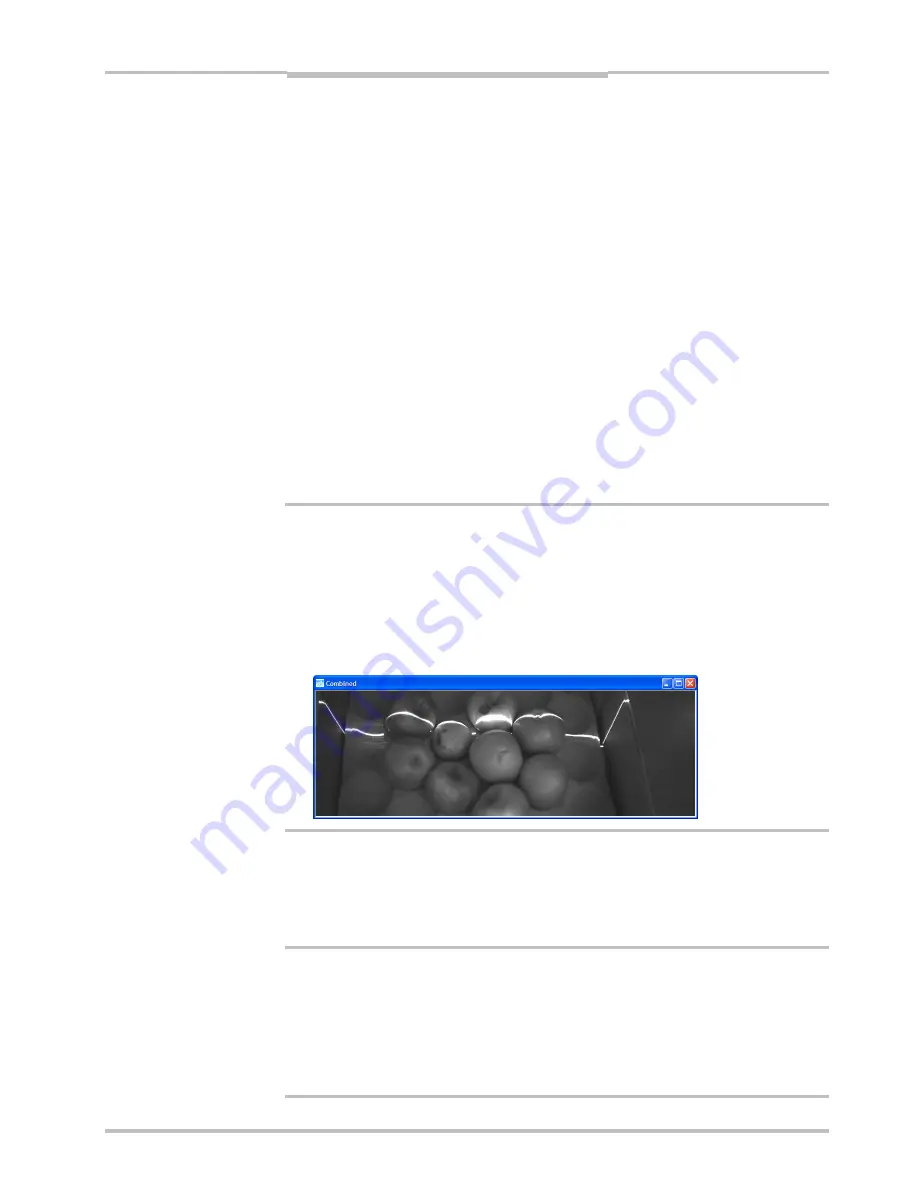
A visualization window appears, but it is still empty.
6.
Click
Start
to start the acquisition.
The visualization window shows the live view of the Ruler.
The view in the visualization window can be used for finding an appropriate exposure time
or the region-of-interest.
4.4.2
Adjust Exposure Time
T
o adjust the exposure time, Ranger Studio should already be connected to the Ruler.
1.
Click
Parameter Editor
in the Ranger Studio.
2.
If needed, expand the parameter tree by clicking on the +-signs.
3.
Select the
Image 1
component in the parameter tree.
All parameters for this component are listed to the right.
4.
Select
Exposure time
and change the value until the laser line is visible in the Visuali-
zation window, but not much else of the scene is. This means that the area not hit by
laser light should not be visible.
SICK IVP • Industrial Sensors • www.sickivp.com • All rights reserved
35


