background image

- 17 -

Step 6.

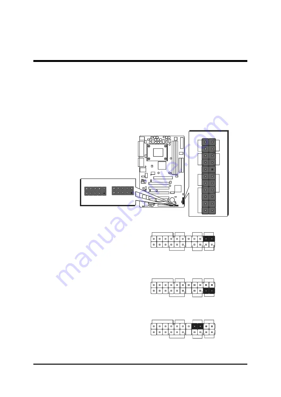
Connect Front Panel Switches/LEDs/Speaker/USB

You can find there are several different cables already existing in the system

case and originating from the computer's front-panel devices (HDD LED,

Power LED, Reset Switch, PC Speaker, or USB devices etc.) These cables

serve to connect the front-panel switches, LEDs, and USB connectors to the

mainboard's front-panel connectors group (J1 and USB2/3), as shown below.

2. Green LED/Power LED (GLED/PLED)

1. HDD-LED (HLED)

3. Hardware Reset Switch Button (Reset)

J 1

+

+

-

-

E

P

M

I

R

es

e

t

S

p

eak

er

P

W

O

N

P

LE

D

1

H

LE

D

U S B 2

1

U S B  3  &   4

U S B 3

1

U S B  5  &   6

G

LE

D

/P

LE

D

J 1

G L E D / P L E D

H L E D

+

+

+

-

-

-

E P M I

R e s e t

S p e a k e r

P W O N

P L E D

1

G L E D /P L E D

J 1

H L E D

+

+

+

-

-

-

E P M I

R e s e t

S p e a k e r

P W O N

P L E D

1

G L E D /P L E D

J 1

H L E D

+

+

+

-

-

-

E P M I

R e s e t

S p e a k e r

P W O N

P L E D

1

Summary of Contents for AV49

Page 1: ...AV49 AV49N Socket 478 Pentium 4 Celeron 478 pin Processor with 400 533 MHz FSB Based MAIN BOARD User s Manual ...

Page 2: ...ed for reliability however no guarantee is given as to the correctness of the contents In the interest of continued product improvement this company reserves the right to revise the manual or include changes in the specifications of the product described within it at any time without notice and without obligation to notify any person of such revision or changes The information contained in this ma...

Page 3: ...EP 1 Install the CPU 12 STEP 2 Set Jumpers 14 STEP 3 Install DDR SDRAM System Memory 14 STEP 4 Install Peripherals in System Case 15 STEP 5 Mount the Mainboard on the Computer Chassis 16 STEP 6 Connect Front Panel Switches LEDs Speaker USB 17 STEP 7 Connect IDE and Floppy Disk Drives 19 STEP 8 Connect Other Internal Peripherals 20 STEP 9 Connect the Power Supply 21 STEP 10 Install Add on Cards in ...

Page 4: ...ort Connector 32 COM1 2 Port Connectors 32 Line Out Front Out Port Connector 32 Line In Rear Out Port Connector 33 Mic In Port Connector 33 MIDI GAME Port Connector 33 USB1 USB2 Port Connectors 33 LAN Port Connectors AV49N Only 33 Front Panel Connectors HDD LED Connector H LED 34 Green LED Power LED Connector G LED PLED 34 Hardware Reset Connector Reset 35 ATX Power On Off Switch Connector PWON 35...

Page 5: ...iary IN Connector J9 White 42 SPDIF J4 42 Audio Center Bass_Out Header J6 43 IR Header J3 43 3 3 SYSTEM MEMORY CONFIGURATION 44 1 INSTALL MEMORY 44 2 UPGRADE MEMORY 44 4 SOFTWARE UTILITY 45 4 1 Mainboard CD Overview 45 4 2 Install Mainboard Software 46 4 2 A Install VIA Driver 47 4 2 B Install Audio Device Driver 48 4 2 C Install USB 2 0 Driver 49 4 2 D Install LAN Driver AV49N Only 50 4 3 View th...

Page 6: ...RATED PERIPHERALS 67 POWER MANAGEMENT SETUP 71 PNP PCI CONFIGURATION 76 PC HEALTH STATUS 78 FREQUENCY VOLTAGE CONTROL 79 LOAD FAIL SAFE DEFAULTS 80 LOAD OPTIMIZED DEFAULTS 80 SET SUPERVISOR PASSWORD 81 SET USER PASSWORD 81 SAVE EXIT SETUP 83 EXIT WITHOUT SAVING 83 ...

Page 7: ...Jumper Settings A Closer Look Page 26 Drivers Software Utilities How to Install Page 45 BIOS Setup How to Configure Page 52 About This Manual For First Time DIY System Builder Page 6 For Experienced DIY User Page 6 For System Integrator Page 6 WHAT S IN THE MANUAL ...

Page 8: ...of onboard functions the highly integrated AV49 AV49N mainboard provides you with a total solution to build the most stable and reli able system Refer to sections 3 2 Jumper Settings 3 2 Jumper Settings 3 2 Jumper Settings 3 2 Jumper Settings 3 2 Jumper Settings and Chapter 4 Drivers Chapter 4 Drivers Chapter 4 Drivers Chapter 4 Drivers Chapter 4 Drivers Software Utilities Software Utilities Softw...

Page 9: ... ports USB Cable optional optional optional optional optional One piece of Audio Cable Center Bass Channel I O Shielding AV49 AV49N User s Manual One piece of Bundled CD ROM with containing Ø AV49 N user s manual saved in PDF format Ø VIA 4 IN 1 driver Ø AC97 Audio driver Ø VIA LAN driver Ø USB 2 0 driver Ø Award Flashing Utility UKN 20L 022 012 7 950 202C F I T 8712F A 9944 D X S M A 4500 02 16CD...

Page 10: ...ory Support Three 184 pin DIMM slots to support up to 3GB of PC1600 PC2100 or PC2700 compliant DDR SDRAM module PCI Expansion Slots Provides five 32 bit PCI slots AGP Expansion Slots Provides one 32 bit AGP slot which supports up to 1X 2X 4X 8X AGP devices 6 USB Interface Onboard Ø 2 USB connectors on back panel and two sets of dual USB ports header on mid board I O Interface Provides a variety of...

Page 11: ...nts data transfer speeds of up to 133 100 133 100 133 100 133 100 133 100 MB sec and also supports Enhanced PIO Modes 80 pin Cable Backward Compatible Legacy ATAPI Devices ATAPI IDE CD ROM CD R CD RW and LS 120 Supports ATX Power Supply Connector ATX power supply unit can connected to the onboard 20 pin Pentium 4 standard ATX power connectors supporting Suspend and Soft On Off by dual function pow...

Page 12: ... item allows users to adjust CPU Host Clock in BIOS Ø CPU Multiplier Setting CPU Multiplier Setting CPU Multiplier Setting CPU Multiplier Setting CPU Multiplier Setting This item allows users to adjust CPU Multiplier in BIOS Intelligent Features Ø Voltage Monitoring Voltage Monitoring Voltage Monitoring Voltage Monitoring Voltage Monitoring Monitors various voltages of key elements such as the CPU...

Page 13: ...s Then follow these steps designed to guide you through a quick and correct installation of your system 3 1 Step by Step Installation Accessories Of AV49 AV49N 3 HARDWARE INSTALLATION UKN20L 02 2 0127 9502 02C F IT 87 12 F A 9 94 4 D XS M A4 500 0216CD TAIW AN 23A1009406 VT8235 2 IA 2 0 03 6 2 2 0 2 17 C D TAI W A N P 4 X 4 0 0 U KN2 0L 02 2 0 12 7 9 50 20 2 CF Serial Port Connector COM1 I O Contr...

Page 14: ... series CPU Please follow the step as below to finish CPU installation Be careful of CPU orientation when you plug it into CPU socket 1 Pull up the CPU socket lever and up to 90 degree angle 2 Locate Pin 1 in the socket and look for a black dot or cut edge on the CPU upper interface Match Pin 1 and cut edge then insert the CPU into the socket ...

Page 15: ... it installed Plug the cable through the heatsink fan in the CPU fan power connector located nearby Note that there are several types of CPU fan connectors Normally if your mainboard supports the hard ware moni toring function a 3 pin fan power connector should allow your system to detect the CPU fan s speed The CPU fan can also run with a 2 pin fan power connector however detection of CPU fan s s...

Page 16: ... procedures The factory set default settings are tuned for opti mum system performance For the advanced users who wish to customize their system section 3 2 Jumper Settings 3 2 Jumper Settings 3 2 Jumper Settings 3 2 Jumper Settings 3 2 Jumper Settings will provide detailed information on how to configure your mainboard manually Step 3 Install DDR SDRAM System Memory To install memory insert DDR S...

Page 17: ...each device according to the instructions provided by the manufacturer IDE devices HDD and CD ROM have to set jumpers to Master or Slave mode depending on whether you install more than one device of each kind 2 Connect IDE cable and FDD cable on the back panel of the internal pe ripheral devices to the corresponding headers on board Note that the cable should be oriented with its colored stripe us...

Page 18: ...mainboard The studs are used to fix the mainboard and to keep a certain distance between the system chassis and the mainboard in order to avoid any electrical shorts between the board and the metal frame of the chassis If your computer case is already equipped with mounting studs you will need to tighten screws to attach the mainboard Note Note Note Note Note In most computer housings you will be ...

Page 19: ...anel switches LEDs and USB connectors to the mainboard s front panel connectors group J1 and USB2 3 as shown below 2 Green LED Power LED GLED PLED 1 HDD LED HLED 3 Hardware Reset Switch Button Reset J1 E P M I R e s e t S p e a k e r P W O N P L E D 1 H L E D USB2 1 USB 3 4 USB3 1 USB 5 6 G L E D P L E D J1 G LE D P LE D H LE D E P M I R eset S peaker P W O N P LE D 1 G LE D P LE D J1 H LE D E P M...

Page 20: ... ATA D ATA 5V 5 V K E Y K EY G N D G N D D ATA D ATA D ATA D ATA 5 V 5V 1 1 USB port 3 USB port 5 USB port 4 USB port 6 G LE D P LE D J1 H LE D E P M I R eset S peaker P W O N P LE D 1 G LE D P LE D J1 H LE D E P M I R eset S peaker P W O N P LE D 1 G LE D P LE D J1 H LE D E P M I R eset S peaker P W O N P LE D 1 G LE D P LE D J1 H LE D E P M I R eset S peaker P W O N P LE D 1 ...

Page 21: ... 19 Step 7 Connect IDE and Floppy Disk Drives 1 IDE cable connector 2 Floppy cable connector IDE 1 IDE 2 1 1 1 FDD1 ...

Page 22: ... 20 Step 8 Connect Other Internal Peripherals 1 Auxiliary IN CD IN Bass Center Out connectors 2 IR header J9 J6 1 AUX_IN J8 J7 CD_INP Bass Center Out CD_IN 1 IR JP3 ...

Page 23: ... 21 Step 9 Connect the Power Supply 1 System power connector 3 Wake On LAN headers 1 WOL ATX2 ATX1 ...

Page 24: ... 22 Step 10 Install Add on Cards in Expansion Slots 1 Accelerated Graphics Port AGP Card 2 PCI Card ...

Page 25: ... case back together and get on to the external peripherals connections to your system back panel 1 PS 2 Mouse and PS 2 Keyboard 2 COM1 Port 3 COM2 Port 4 Parallel Port 5 Audio Line Out Line In Mic In Ports 6 MIDI GAME Port 7 LAN Port 8 USB port 1 USB port 2 foxconn 7 8 6 2 3 1 5 4 V G A P R T ...

Page 26: ...xtended partition The FDISK utility will assign a drive letter i e C D E to each partition which will be shown in the FDISK program After FDISK procedure reboot your system by using the same system floppy disk Note Note Note Note Note DOS 6 2x and Windows 95A can only support up to 2 1GB of HDD partition If you use the FDISK utility with one of the opera ting systems mentioned above you can only i...

Page 27: ...V49 AV49N bundled CD ROM into your CD ROM drive The auto run program will display the drivers main installation window on screen 2 Select the Install Mainboard Software bar to run into sub menu 3 Choose Install VIA Driver and complete it 4 Choose Install Audio Device Driver and complete it 5 Choose Install USB2 0 Driver and complete it 6 Choose Install LAN Driver AV49N and complete it 7 Return to ...

Page 28: ...Jumpers with two pins are shown as for Close On or for Open Off To Short jumper pins simply place a plastic mini jumpers over the desired pair of pins Caution Caution Caution Caution Caution 1 Do not remove the mainboard from its antistatic protective packaging until you are ready to install it 2 Carefully hold the mainboard by its edges and avoid touching its components When putting the mainboard...

Page 29: ...y jumpers slots and connectors along with their assigned functions CPU Memory Expansion Slots Socket478 CPU Socket for Pentium 4 processors DIMM1 2 3 Four DIMM Slots for 64 128 256 512 MB and 1GB of 2 5V DDR SDRAM The total installed memory does not exceed 3GB AGP One AGP Accelerated Graphics Port Slot PCI Five 32 bit PCI Expansion Slots B2 B3 C1 C7 A1 E1 A2 E2 A3 A4 B1 B4 B7 B8 B9 C8 D1 D1 E2 A3 ...

Page 30: ...SB Universal Serial Bus ports LAN RJ 45 LAN port Front Panel Connectors HDD LED IDE drive active LED Green LED Green LED Reset Hardware reset switch Power ON ATX power on off momentary type switch EPMI System Management Interface Power LED System power LED SPEAKER Internal speaker in housing USB2 3 Extended USB header Internal Peripherals Connectors FDD1 Floppy disk drive interface IDE1 IDE primar...

Page 31: ... FAN2 Chipset fan connector FAN3 System fan connector WOL Wake On LAN connector J5 Front Panel Audio connector J7 J8 CD_IN connector J9 Auxiliary_IN connector J4 SPDIF J6 Center Bass J3 IR connector E2 E4 E5 E6 E2 E2 E7 E3 E8 E9 ...

Page 32: ...p 3 Step 3 Step 3 Step 3 Remove jumper cap from JP1 pins 1 2 Step 4 Step 4 Step 4 Step 4 Step 4 Place the jumper cap on JP1 pin 2 3 for a few seconds Step 5 Step 5 Step 5 Step 5 Step 5 Return the jumper cap to pin 1 2 Step 6 Step 6 Step 6 Step 6 Step 6 Plug ATX Power cable into ATX Power connector Step 7 Step 7 Step 7 Step 7 Step 7 Turn on the system power PC On A1 1 1 FSB Speed configuration Sett...

Page 33: ...Protected Pin 2 3 Default Unprotected A4 1 1 USB Power on Setting JP3 4 AV49 AV49N provides jumpers to set USB devices which connect to backe panel tp power on system from ACPI S3 to S5 stage Place jumper cap on JP3 or JP4 pin 1 2 for enabling or disabling USB device USB port3 USB port6 power on function Pin 1 2 Disable USB power on function Pin 2 3 Enable USB power on function A3 1 1 JP4 JP3 1 1 ...

Page 34: ...ponding con nectors Parallel Port Connector One DB25 female parallel connector is lo cated at the rear panel of the mainboard Plug the connection cable from your par allel device printer scanner etc into this connector COM1 2 Port Connectors This mainboard can accommodate two serial device on COM1 2 Attach a serial device cable to the DB9 serial port COM1 2 at the back panel of your computer Line ...

Page 35: ... Instrument Connection MIDI Instrument Connection MIDI Instrument Connection MIDI Instrument Connection MIDI Instrument Connection You will need a MIDI adapter to connect a MIDI compatible instrument to the sound card The MIDI adapter can in turn be connected to the Joystick MIDI port You will also need the MIDI sequencing software to run MIDI instruments with your computer etc into this connector...

Page 36: ...en LED or Power LED the header can be in these states The Green LED indicates that the system is currently in one of the power saving mode Doze Stand by Suspend When the system resumes to normal opera tion mode the Green LED will go off power LEN on This Power LED will go off during power saving mode Attach a 2 pin Green LED Power LED cable to GLED PLED header C2 C1 J1 G L E D P L E D E P M I R e ...

Page 37: ...to the Reset header Pressing the reset switch causes the system to restart ATX Power On Off Switch Connector PWON The Power On Off Switch is a momentary type switch used for turning on or off the system ATX power supply Attach the connector cable from the Power Switch to the 2 pin Power ON header on the mainboard J1 G L E D P L E D E P M I R e s e t S p e a k e r P W O N P L E D 1 H L E D J1 G L E...

Page 38: ... to resume back the normal operation situation Power LED Connector PLED Attach the 3 pin Power LED connector cable from the housing front panel to the Power LED header on the mainboard The power LED stays light while the system is on J1 G L E D P L E D E P M I R e s e t S p e a k e r P W O N P L E D 1 H L E D J1 G L E D P L E D E P M I R e s e t S p e a k e r P W O N P L E D 1 H L E D ...

Page 39: ... e r P W O N P L E D 1 H L E D Extended USB Headers USB2 3 The headers are used to connect the cable attached to USB connectors which are mounted on front panel or back panel But the USB cable is op tional at the time of purchase Pins Assignment 1 POWER 2 POWER 3 DATA 4 DATA 5 DATA 6 DATA 7 GND 8 GND 9 KEY 10 NC USB2 1 USB 3 4 USB3 1 USB 5 6 1 3 5 7 9 2 4 6 8 10 ...

Page 40: ... This mainboard also includes one 34 pin floppy disk controller FDD1 to accommodate the Floppy Disk Drive FDD Moreover this mainboard comes with one 80 pin ATA 133 100 133 100 133 100 133 100 133 100 ribbon cable to connect to IDE H D D and one 34 pin ribbon cable for F D D connection D1 Important Important Important Important Important Ribbon cables are directional therefore make sure to always c...

Page 41: ...wer Auto Recovery function to solve this problem You may enable the function PWRON After PWR Fail that is under sub menu of Power Mangement Setup through BIOS setup program Note 1 Note 1 Note 1 Note 1 Note 1 The ATX power connector is directional and will not go in unless the guides match perfectly making sure that pin 1 is properly positioned Note 2 Note 2 Note 2 Note 2 Note 2 Make sure the latch...

Page 42: ...which depends on the fan maker Keep in mind that the red wire should always be connected to the 12V header and the black wire to the ground GND header SENSE GND 12V 1 FAN1 FAN2 FAN3 with rotate sense Wake On LAN Connector WOL Attach a 3 pin connector through the LAN card which supports the Wake On LAN WOL function This function lets users wake up the connected system through the LAN card Pins Assi...

Page 43: ...L 2 CD GND 3 CD GND 4 CD R Front Panel Audio Header J5 This connector is used to attach to Audio equipment embedded into or at tached to the case Pins Assignment 1 MIC 2 AGND 3 FLOR 4 LNR 5 FLOL 6 LNL 7 AGND 8 KEY 9 FLOL 10 FNL Two mini jumpers must be setted on pin 5 6 and pin 9 10 when this header is not used 1 Front Audio JP5 2 1 7 5 3 4 6 8 9 10 2 1 7 5 3 4 6 8 9 10 J8 J7 CD_INP CD_IN 1 4 3 2 ...

Page 44: ...udio input from CD ROM TV tuner or MPEG card Pin Assignments 1 AUXL 2 AGND 3 AGND 4 AUXR SPDIF J4 Port J4 can be used to connect special device J9 AUX_IN 1 4 3 2 1 SPDIF J4 9 10 4 6 8 7 5 3 2 1 Pin Assignments 1 12V 2 VCC 3 N A 4 SPDIF OUT 5 SPDIF IN Optional 6 GND 7 N A 8 N A 9 KEY 10 GND ...

Page 45: ... Note Note Note Note Note Before connect your IR device please be sure each IR on board pin allocation is matchable with the pin of the IR device Otherwise incorrect IR connection may do damage to your IR device Step 1 Step 1 Step 1 Step 1 Step 1 Attach the 5 pin infrared device cable to LSIR1 Refer to the above diagram for IR pin assignment Step 2 Step 2 Step 2 Step 2 Step 2 This mainboard suppor...

Page 46: ... BIOS utility can detect the system memory automatically You can check the total system memory value in the BIOS Standard CMOS Setup menu 2 Upgrade Memory You can easily upgrade the system memory by inserting additional DDR SDRAM modules in available DIMM banks The total system memory is calculated by simply adding up the memory in all DIMM banks After upgrade the new system memory value will auto...

Page 47: ...Software Install Mainboard AV49 Software Install Mainboard AV49 Software Install Mainboard AV49 Software Installing VIA Audio device and USB2 0 drivers F Install Mainboard AV49N Software Install Mainboard AV49N Software Install Mainboard AV49N Software Install Mainboard AV49N Software Install Mainboard AV49N Software Installing VIA Audio device LAN and USB2 0 drivers F Manual Manual Manual Manual ...

Page 48: ...ware bar or Install Mainboard AV49N Software Install Mainboard AV49N Software Install Mainboard AV49N Software Install Mainboard AV49N Software Install Mainboard AV49N Software to run into sub menu The Mainboard AV49 Software Mainboard AV49 Software Mainboard AV49 Software Mainboard AV49 Software Mainboard AV49 Software include 4 2 A 4 2 A 4 2 A 4 2 A 4 2 A Install VIA Driver 4 2 B 4 2 B 4 2 B 4 2...

Page 49: ...oftware Shuttle Mainboard Software Shuttle Mainboard Software Shuttle Mainboard Software Setup Setup Setup Setup Setup screen Use your pointing device e g mouse to select Install VIA Driver Install VIA Driver Install VIA Driver Install VIA Driver Install VIA Driver bar to install VIA driver Once you made your selection a Setup window run the installation automatically When the copying files is don...

Page 50: ...l Audio Device Install Audio Device Install Audio Device Driver Driver Driver Driver Driver bar to install audio device driver Once you made your selection a Setup window run the installation automatically When the copying files is done make sure you reboot reboot reboot reboot reboot the system to take the installation effect AV49 AV49N ...

Page 51: ...ou made your selection a Setup window run the installation automatically When the copying files is done make sure you reboot reboot reboot reboot reboot the system to take the installation effect Note The WinNT don t need install this driver Note The WinNT don t need install this driver Note The WinNT don t need install this driver Note The WinNT don t need install this driver Note The WinNT don t...

Page 52: ...river Once you made your selection a Setup window run the installation automatically When the copying files is done make sure you reboot reboot reboot reboot reboot the system to take the installation effect Note The WinNT don t need install this driver Note The WinNT don t need install this driver Note The WinNT don t need install this driver Note The WinNT don t need install this driver Note The...

Page 53: ... Mainboard Software Setup Setup Setup Setup Setup screen Select using your pointing device e g mouse on the Manual Manual Manual Manual Manual bar Then Online Information Online Information Online Information Online Information Online Information windows will appear on your screen Click on the Install Acrobe Reader Install Acrobe Reader Install Acrobe Reader Install Acrobe Reader Install Acrobe Re...

Page 54: ...ess DEL to enter SETUP or simultaneously press Ctrl Alt Esc keys Note 1 Note 1 Note 1 Note 1 Note 1 If you miss trains of words meationed in step2 the message disap pears before you can respond and you still wish to enter BIOS Setup restart the system and try again by turning the computer OFF and ON again or by pressing the RESET switch located at the computer s front panel You may also reboot by ...

Page 55: ...reen Setup Items The main menu includes the following main setup categories Recall that some systems may not include all entries Standard CMOS Features Use this menu for basic system configuration Advanced BIOS Features Use this menu to set the Advanced Features available on your system Advanced Chipset Features Use this menu to change the values in the chipset registers and opti mize your system ...

Page 56: ...to operate Load Optimized Defaults Use this menu to load the BIOS default values that are factory set for optimal performance system operation While Award has designed the custom BIOS to maximize performance the factory has the right to change these defaults to meet users needs Supervisor User Password Use this menu to change set or disable supervisor user password It allows you to limit access to...

Page 57: ...The time is converted based on the 24 hour military time clock For example 5 p m is 17 00 00 IDE Primary Master IDE Primary Master IDE Primary Master IDE Primary Master IDE Primary Master Options are in its sub menu Press Enter to enter the sub menu of detailed options IDE Primary Slave IDE Primary Slave IDE Primary Slave IDE Primary Slave IDE Primary Slave Options are in its sub menu Press Enter ...

Page 58: ...ice EGA VGA CGA 40 CGA 80 or MONO Halt On Halt On Halt On Halt On Halt On Select the situation in which you want the BIOS to stop the POST process and notify you Ø The choice All Errors No Errors All But Keyboard All But Diskette or All But Disk Key Base Memory Base Memory Base Memory Base Memory Base Memory Displays the amount of conventional memory detected during boot up Ø The choice N A Extend...

Page 59: ...s etc Note PRECOMP 65535 means NONE Ø The choice None Auto or Manual Access Mode Access Mode Access Mode Access Mode Access Mode Choose the access mode for this hard disk Ø The choice CHS LBA Large or Auto Capacity Capacity Capacity Capacity Capacity Disk drive capacity Approximated Note that this size is usually slightly greater than the size of a formatted disk given by a disk checking program Ø...

Page 60: ... 58 Landing zone Landing zone Landing zone Landing zone Landing zone Set the Landing zone size Ø Min 0 Max 65535 Sector Sector Sector Sector Sector Number of sector per track Ø Min 0 Max 255 ...

Page 61: ...the system boots up caus ing a warning message to appear when anything at tempts to access the boot sector or hard disk partition table Disabled Disabled Disabled Disabled Disabled No warning message will appear when anything attempts to access the boot sector or hard disk partition table Ø The choice Enabled or Disabled CPU L1 L2 Cache CPU L1 L2 Cache CPU L1 L2 Cache CPU L1 L2 Cache CPU L1 L2 Cac...

Page 62: ...ap Floppy Drive Swap Floppy Drive If the system has two floppy drives you can swap the logical drive name assignment Ø The choice Enabled or Disabled Boot Up Floppy Seek Boot Up Floppy Seek Boot Up Floppy Seek Boot Up Floppy Seek Boot Up Floppy Seek Seeks disk drives during boot up Disabling speed boots up Ø The choice Enabled or Disabled Boot Up NumLock Status Boot Up NumLock Status Boot Up NumLo...

Page 63: ... security select PASSWORD SETTING at Main Menu and then you will be asked to enter password Do not type anything and just press Enter it will disable security Once the security is disabled the system will boot and you can enter Setup freely OS Select For DRAM 64MB OS Select For DRAM 64MB OS Select For DRAM 64MB OS Select For DRAM 64MB OS Select For DRAM 64MB Selects the operating system that is ru...

Page 64: ...ive Control DRAM Clock Drive Control DRAM Clock Drive Control DRAM Clock Drive Control Options are in its sub menu Press Enter to enter the sub menu of detailed options Current FSB Frequency Current FSB Frequency Current FSB Frequency Current FSB Frequency Current FSB Frequency This item show Current CPU Front Side Bus speed Current DRAM Frequency Current DRAM Frequency Current DRAM Frequency Curr...

Page 65: ...The Choice 2T or 3T Active to Precharge Tras Active to Precharge Tras Active to Precharge Tras Active to Precharge Tras Active to Precharge Tras This item allows you to Active Command to Precharge Command Period Ø The Choice 6T or 7T Active to CMD Trcd Active to CMD Trcd Active to CMD Trcd Active to CMD Trcd Active to CMD Trcd This item allows you to Active to CMD Ø The Choice 2T or 3T DRAM Comman...

Page 66: ...es an end user to manually select the AGP output buffer drive strength Ø Key in a HEX number Min 0000 Max 00FF AGP Fast Write AGP Fast Write AGP Fast Write AGP Fast Write AGP Fast Write Enable or Disable the AGP Fast Write faster Ø The Choice Enabled or Disabled AGP Master 1 WS Write AGP Master 1 WS Write AGP Master 1 WS Write AGP Master 1 WS Write AGP Master 1 WS Write When this item enabled writ...

Page 67: ...osted write buffer to support delay transactions cycles Select Enabled to support compliance with PCI specification version 2 1 Ø The Choice Enabled or Disabled VLink 8X Support VLink 8X Support VLink 8X Support VLink 8X Support VLink 8X Support Enable this item will set VLink 8X transfer mode Disable it will set VLink 4X transfer mode Ø The Choice Enabled or Disabled Memory Hole Memory Hole Memor...

Page 68: ... Delay Prior to Thermal Delay Prior to Thermal Delay Prior to Thermal Delay Prior to Thermal This item select the Delay time before thermal controller activate from temperature too high Ø The Choice 4 Min 8 Min 16 Min or 32 Min ...

Page 69: ...nChip IDE Channel1 OnChip IDE Channel1 OnChip IDE Channel1 OnChip IDE Channel1 The chipset contains a PCI IDE interface with support to two IDE channels Select Enabled to activate the secondary IDE interface select Disabled to deactivate this interface Ø The choice Enabled or Disabled IDE Prefetch Mode IDE Prefetch Mode IDE Prefetch Mode IDE Prefetch Mode IDE Prefetch Mode The onboard IDE drive in...

Page 70: ...CI Device VIA OnChip PCI Device VIA OnChip PCI Device Options are in its sub menu Press Enter to enter the sub menu of detailed options OnBoard AC97 Audio OnBoard AC97 Audio OnBoard AC97 Audio OnBoard AC97 Audio OnBoard AC97 Audio Enables and disables the onboard audio chip Disable this item if you are going to install a PCI audio add on card Ø The choice Auto or Disabled VIA 3043 OnChip LAN VIA 3...

Page 71: ...ode Parallel Port Mode Parallel Port Mode Parallel Port Mode Parallel Port Mode Select an operating mode for the onboard parallel printer port Select Normal Compatible or SPP unless you are certain your hardware and software both support one of the other available modes Ø The choice SPP EPP ECP or ECP EPP ECP Mode Use DMA ECP Mode Use DMA ECP Mode Use DMA ECP Mode Use DMA ECP Mode Use DMA Select a...

Page 72: ...Universal Serial Bus USB controller and you have a USB keyboard Ø The Choice Enabled or Disabled USB Mouse Support USB Mouse Support USB Mouse Support USB Mouse Support USB Mouse Support Select Enabled if your system contains a Universal Serial Bus USB controller and you have a USB Mouse Ø The Choice Enabled or Disabled IDE HDD Block Mode IDE HDD Block Mode IDE HDD Block Mode IDE HDD Block Mode ID...

Page 73: ...Type This item allows you to select sleep state when suspend Ø The choice S1 POS S3 STR or S1 S3 Power Management Option Power Management Option Power Management Option Power Management Option Power Management Option This category allows you to select the type or degree of power saving mode settings User Define User Define User Define User Define User Define Allows you to set each mode individuall...

Page 74: ...ng mode Always On Always On Always On Always On Always On Monitor will remain on during power saving mode Suspend Off Suspend Off Suspend Off Suspend Off Suspend Off Monitor is blanked when the system enters the Suspend mode Ø The choice Always On or Suspend off Video Off Method Video Off Method Video Off Method Video Off Method Video Off Method This determines the manner in which the monitor is b...

Page 75: ...Event Activity Detect IRQ Event Activity Detect Options are in its sub menu Press Enter to enter the sub menu of detailed options USB Resume from S3 USB Resume from S3 USB Resume from S3 USB Resume from S3 USB Resume from S3 Set the item Enabled users can awaken the system by USB keyboard When ACPI Suspend Type item select is S1 POS then this item can not showup Ø The choice Disabled or Enabled VG...

Page 76: ...date Ø Key in a DEC number Min 0 Max 31 Resume Time hh mm ss Resume Time hh mm ss Resume Time hh mm ss Resume Time hh mm ss Resume Time hh mm ss This item selects the alarm Time hh Ø Key in a DEC number Min 0 Max 23 mm ss Ø Key in a DEC number Min 0 Max 59 IRQs Activity Monitoring IRQs Activity Monitoring IRQs Activity Monitoring IRQs Activity Monitoring IRQs Activity Monitoring Primary INTR Prima...

Page 77: ...9 IRQ2 Redir IRQ9 IRQ2 Redir IRQ9 IRQ2 Redir IRQ9 IRQ2 Redir IRQ9 IRQ2 Redir IRQ10 Reserved IRQ10 Reserved IRQ10 Reserved IRQ10 Reserved IRQ10 Reserved IRQ11 Reserved IRQ11 Reserved IRQ11 Reserved IRQ11 Reserved IRQ11 Reserved IRQ12 PS 2 Mouse IRQ12 PS 2 Mouse IRQ12 PS 2 Mouse IRQ12 PS 2 Mouse IRQ12 PS 2 Mouse IRQ13 Coprocessor IRQ13 Coprocessor IRQ13 Coprocessor IRQ13 Coprocessor IRQ13 Coprocesso...

Page 78: ...Data Normally you leave this field Disabled Select Enabled to reset Extended System Configuration Data ESCD when you exit from Setup if you have installed a new device or software and the system reconfiguration has caused such a serious conflict that the operating system can not boot Ø The choice Enabled or Disabled Resource controlled By Resource controlled By Resource controlled By Resource cont...

Page 79: ...he MPEG ISA VESA VGA Cards can work with PCI VGA or not If you have MPEG ISA VESA VGA Cards and PCI VGA Card worked Enable this field Otherwise please Disable it Ø The choice Enabled or Disabled Assign IRQ For VGA Assign IRQ For VGA Assign IRQ For VGA Assign IRQ For VGA Assign IRQ For VGA This item allows the user to set VGA IRQ Routing table Enabled or Disabled Ø The choice Enabled or Disabled As...

Page 80: ... CPU Voltage FAN2 Speed FAN2 Speed FAN2 Speed FAN2 Speed FAN2 Speed AGP Voltage AGP Voltage AGP Voltage AGP Voltage AGP Voltage FAN3 Speed FAN3 Speed FAN3 Speed FAN3 Speed FAN3 Speed 3 3V VIN 3 3V VIN 3 3V VIN 3 3V VIN 3 3V VIN Vcc 5V IN Vcc 5V IN Vcc 5V IN Vcc 5V IN Vcc 5V IN Vcc 12V IN Vcc 12V IN Vcc 12V IN Vcc 12V IN Vcc 12V IN Vcc 12V IN Vcc 12V IN Vcc 12V IN Vcc 12V IN Vcc 12V IN Chipset Volt...

Page 81: ...to Detect PCI DIMM Clk This item allows you to enable disable auto detection DIMM PCI Clock Ø The choice Enabled or Disabled Spread Spectrum Spread Spectrum Spread Spectrum Spread Spectrum Spread Spectrum This item allows you to enable disable the spread spectrum modulation Ø The choice Enabled or Disabled CPU Clock CPU Clock CPU Clock CPU Clock CPU Clock This item allows the user to adjust CPU Ho...

Page 82: ...N N Pressing Y loads the BIOS default values for the most stable minimal performance system operations Load Optimized Defaults When you press Enter on this item you will get a confirmation dialog box with a message similar to Load Optimized Defaults Y N N Pressing Y loads the default values that are factory set for optimal performance system operation ...

Page 83: ...ode and User mode In general Supervisor mode has full access to the Setup options whereas User mode has restricted access to the options By setting separate Supervisor and User password a system supervisor can limit who can change critical Setup values Enter Password Enter Password Enter Password Enter Password Enter Password Type the password up to eight characters and press Enter The password ty...

Page 84: ... password whenever the system is rebooted or you try to enter Setup If you select Setup at Security Op tion of BIOS Features Setup Menu you will be prompted only when you try to enter Setup Warning Warning Warning Warning Warning Retain a record of your password in a safe place If you forget the password the only way to access the system is to clear CMOS please refer to Clear CMOS on page 30 ...

Page 85: ...next time you boot your computer the BIOS configures your system according to the Setup selections stored in CMOS After saving the values the system is restarted again Exit Without Saving Pressing Enter on this item asks for confirmation Quit without saving Y N Y This allows you to exit from Setup without storing in CMOS any change The previous selections remain in effect This exits from the Setup...

Reviews: