


53
Disassembly and inspection
(1)
Place the nozzle holder (body) in a vice and
disassemble turning the nozzle nut.
NOTE: Take care not to allow the needle valve to
drop when removing the nozzle.
(2) Wash the nozzle and needle valve and check for seizure
and sticking of the nozzle and fuel leakage on the seat
surface. Correct fuel leakage of the seat by lapping.
(3) Check the distance piece upper and lower contact areas
and correct to be sticked closely.
(4) Check the push rod for wear on the nozzle needle valve
contact surface and check the spring seat for crack.
Reassembly and adjustment
(1) When assembling a new nozzle ass’y, heat light oil to
50 - 60°C and remove the rust preventive oil in it. Slide
the body and needle valve to ensure that they slide
lightly.
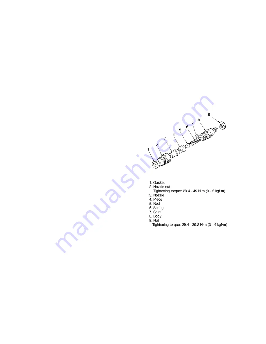
(2) Invert the body, place the shim, spring, rod, piece and
nozzle on it in this order, cover the nozzle nut and
tighten.
(3) After assembly, check for the nozzle injection pressure.
1. Adjust by the adjusting washer (shim) so that the
injection is started at 11.76 MPa (120 kgf/cm
2
)
using a nozzle tester.
2. The pressure increases or decreases about 0.98 MPa
(10 kgf/cm
2
) by a washer of 0.1 mm.
(4) Injection condition
1. Small drops should not be mixed in the spray.
2. The oil should be injected describing a cone by
straight lines toward the center line of the nozzle.
3. Place white paper at about 30 cm from the nozzle
and confirm that the spray is approximately circular
when injected.
4. Keep the oil pressure lower by 1.96 MPa (20
kgf/cm
2
) than the specified value 11.76 MPa (120
kgf/cm
2
) and check that the test oil does not drop
form the nozzle end.
T151
Summary of Contents for ST318
Page 1: ......
Page 4: ...3 Chapter 1 GENERAL...
Page 27: ...26...
Page 28: ...27 Chapter 2 ENGINE Tractor Model Engine Model ST318 S753 ST321 S773 ST324 S773L...
Page 29: ...28 2 1 Engine Sectional View T100 T101...
Page 48: ...47 13 Oil flow T140...
Page 98: ...97 Chapter 3 TRACTOR MAIN BODY...
Page 132: ...131 2 HYDROSTATIC TRANSMISSION 1 SPEED PTO MID PTO 1 Sectional view T505 T506...
Page 154: ...153 Take out the swash plate from the case T566...
Page 194: ...193 Model 9 3 shown...
Page 199: ...198 4 CONTROL VALVE 1 Control valve relief valve 340013400 1 Name of components T658...
Page 203: ...202 2 Control valve for lifting lowering implement 340016110 1 Name of components T667...
Page 223: ...221...
Page 224: ...222...
Page 225: ...223...
Page 226: ...224...
Page 228: ...226 4 LIGHTEING CIRCUIT T702...
Page 229: ...227 5 HORN CIRCUIT T703...
Page 230: ...228 6 FUEL LEVEL CIRCUIT T704...
Page 231: ...229 7 ENGINE STOP SOLENOID CIRCUIT T705...
Page 232: ...230 8 ENGINE COOLANT TEMPERATURE CIRCUIT ENGINE OIL PRESSURE WARNING CIRCUIT T706...
Page 233: ...231 9 HST CRUISE CONTROL CIRCUIT T707...
Page 234: ...232 10 PARKING BRAKE WARNING LIGHT CIRCUIT T708...
Page 235: ...233 11 BRAKE LAMP CIRCUIT T709...
Page 236: ...234 12 SAFETY START CIRCUIT T710...
Page 237: ...235 13 FLASHER AND HAZARD LUMP CIRCUIT T711...
Page 238: ...236 14 GLOW PLUG AND GLOW LAMP CIRCUIT T712...
Page 239: ...237 15 ALTERNATOR AND ENGINE STOP SOLENOID CIRCUIT T713...


