


42
6) Connecting rod metal
Inspection
(1) Check the metal and if peeling, melting, uneven wear,
improper contact or other damage is noticed, replace
the metal.
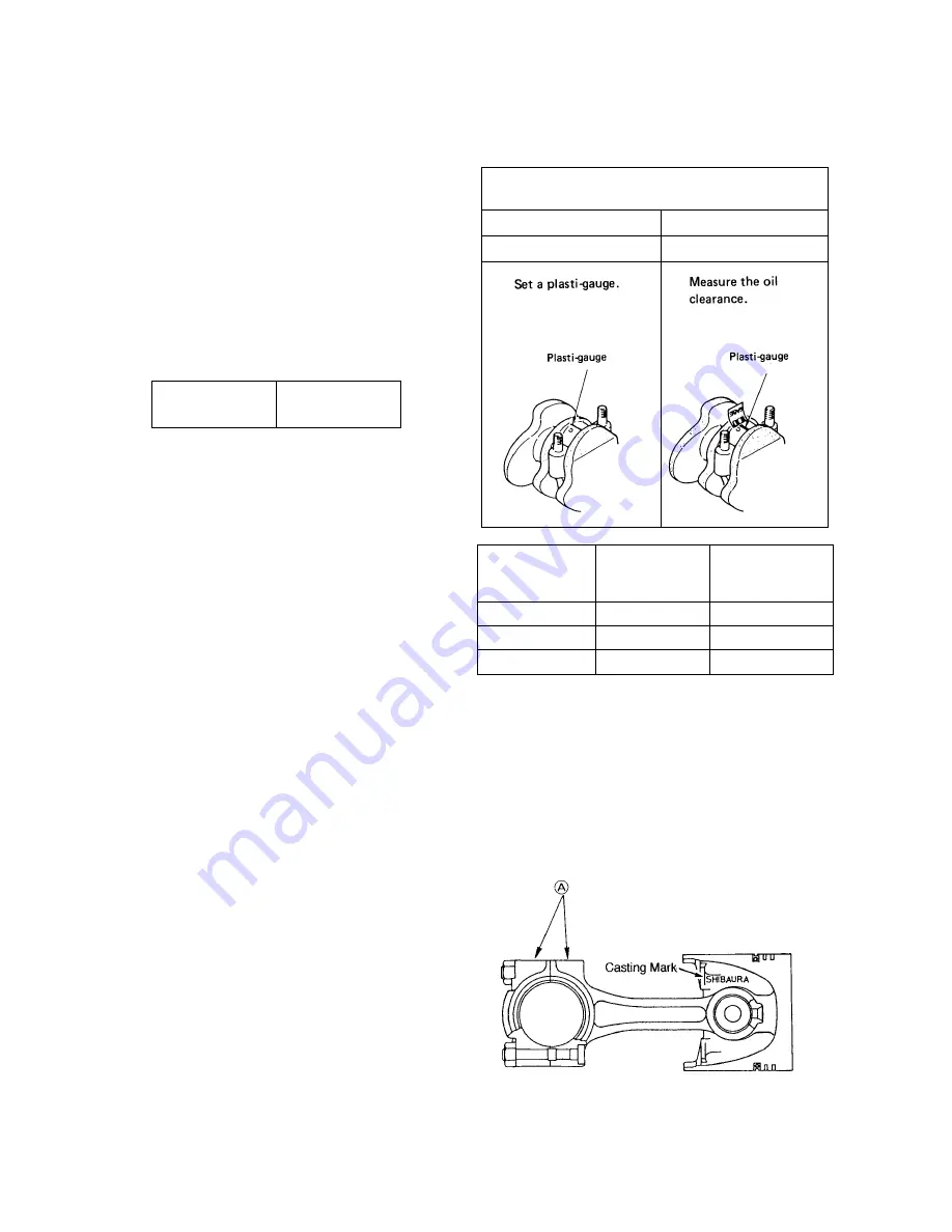
(2) Measure the oil clearance of the crank pin and metal
using plasti-gauge.
➀
Remove oil dust or other foreign matter sticked to
the metal and crank pin.
➁
Cut plasti-gauge to the length same as the metal
width and place it on the crank pin in parallel with
the crankshaft avoiding the oil hole.
➂
Install the connecting rod metal and connecting rod
cap and tighten with the specified tightening torque.
Tightening torque
29 – 34 N
·
m
(3.0 – 3.5 kgf
·
m)
NOTE: Never turn the connecting rod at this time.
➃
Remove the connecting rod cap and measure the
plasti-gauge width with the scale printed on the
gauge envelope.
NOTE: Measure the widest part of the
plasti-gauge.
(3) If the oil clearance exceeds the service limit according
to the result of the measurement, replace the metal or
grind the crank pin and replace with a metal of
undersize.
NOTE:
1. When the crank shaft pin outside is ground,
check the oil clearance before installing it.
2. Grind the crank pin precisely referring to the
paragraph of the crank shaft about the finishing
accuracy and oil holes.
Reassembly (piston and connecting rod)
(1) Heat the piston to about 100°C with a piston heater or
the like and install it aligning the SHIBAURA mark in
the piston and match mark at (A) of the connecting rod.
(2) Care should be taken to the figure match mark at (A) of
the connecting rod.
(3) Install the piston ring to the piston facing the stamp at
the end surface of the ring end gap upward.
(4) When the connecting rod or piston and piston pin are
replaced, weight variation among cylinders with the
rod, piston and piston ring installed should be within
10 g.
Clearance between crank pin and connecting rod metal
(oil clearance) (mm)
Standard assembling value
Service limit
0.035 – 0.083
More than 0.2
T126
T127
Metal size
Metal code No.
Crankshaft pin
outside dia. Finishing
dimension (
∅
)
S.T.D.
198517130 38.964
–
38.975
U.S. 0.25
198517134 38.714
–
38.725
U.S. 0.50
198517137 38.464
–
38.475
T128
Summary of Contents for ST318
Page 1: ......
Page 4: ...3 Chapter 1 GENERAL...
Page 27: ...26...
Page 28: ...27 Chapter 2 ENGINE Tractor Model Engine Model ST318 S753 ST321 S773 ST324 S773L...
Page 29: ...28 2 1 Engine Sectional View T100 T101...
Page 48: ...47 13 Oil flow T140...
Page 98: ...97 Chapter 3 TRACTOR MAIN BODY...
Page 132: ...131 2 HYDROSTATIC TRANSMISSION 1 SPEED PTO MID PTO 1 Sectional view T505 T506...
Page 154: ...153 Take out the swash plate from the case T566...
Page 194: ...193 Model 9 3 shown...
Page 199: ...198 4 CONTROL VALVE 1 Control valve relief valve 340013400 1 Name of components T658...
Page 203: ...202 2 Control valve for lifting lowering implement 340016110 1 Name of components T667...
Page 223: ...221...
Page 224: ...222...
Page 225: ...223...
Page 226: ...224...
Page 228: ...226 4 LIGHTEING CIRCUIT T702...
Page 229: ...227 5 HORN CIRCUIT T703...
Page 230: ...228 6 FUEL LEVEL CIRCUIT T704...
Page 231: ...229 7 ENGINE STOP SOLENOID CIRCUIT T705...
Page 232: ...230 8 ENGINE COOLANT TEMPERATURE CIRCUIT ENGINE OIL PRESSURE WARNING CIRCUIT T706...
Page 233: ...231 9 HST CRUISE CONTROL CIRCUIT T707...
Page 234: ...232 10 PARKING BRAKE WARNING LIGHT CIRCUIT T708...
Page 235: ...233 11 BRAKE LAMP CIRCUIT T709...
Page 236: ...234 12 SAFETY START CIRCUIT T710...
Page 237: ...235 13 FLASHER AND HAZARD LUMP CIRCUIT T711...
Page 238: ...236 14 GLOW PLUG AND GLOW LAMP CIRCUIT T712...
Page 239: ...237 15 ALTERNATOR AND ENGINE STOP SOLENOID CIRCUIT T713...


