background image

62

Useful Features &

Network Function

Setting Up the Optional Boards

Network Function

Three optional Expansion Boards from Sharp are also available for specialised application. Please see your local
Sharp Authorised LCD Projector Dealer for details on these boards. Be sure to have service personnel install
optional boards.

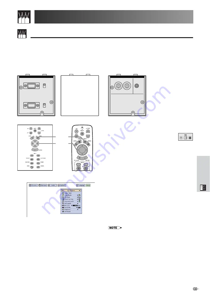
Boards for Network Capability

LAN Board

RS-422 Board

Expansion Video Board

SDI (Serial Digital Interface)

RS-422 CONTROL

INPUT

DISABLE

ENABLE

DISABLE

ENABLE

OUTPUT

Soon-to-be-released

The

Optional Board

 function allows you to set and

confirm the optional boards.

(Slide the 

MOUSE/ADJUSTMENT

 switch

on the remote control to the ADJ. position.)

1

Press 

MENU

.

2

Press 

ß

/

©

 to select “Options (2)”.

3

Press 

/

ƒ

 to select “Optional Board”.

4

To exit from the GUI, press 

MENU

.

The type of board and the board status are displayed
as shown below.

• LAN Board (10BASE-T)

Set the IP Address, Gateway and Subnet mask in
accordance with the sub menu.

SDI Board

The status of the SDI Board is displayed.

• RS-422 Board

The input and output control signals are displayed.

• For details on intended purpose, see the optional boards

operation manuals.

MOUSE

ADJ.

1.2.3

4.5.6

1

,

4

2

,

3

Projector

Remote Control

(GUI) On-screen Display

INPUT 6     SDI

INPUT

OUTPUT

AUDIO

INPUT

e.g. when installing SDI board

Summary of Contents for XG-V10XE

Page 1: ...nt Information Setup Connections Operation Buttons Basic Operation Maintenance Troubleshooting Appendix Useful Features Network Function Lenses are sold separately OPERATION MANUAL MODEL XG V10XE LCD PROJECTOR ...

Page 2: ...irettive 89 336 EEC e 73 23 EEC come emendata dalla direttiva 93 68 EEC Â Í Ù ÛÙ ÛÁ ıÙfi ÌÙ ÔÍÒflÌÂÙ È ÛÙÈÚ ÈÙfiÛÂÈÚ Ù Ì Ô Á È Ì ÙÁÚ EıÒ ÍfiÚ EÌ ÛÁÚ 89 336 EOK Í È 73 23 EOK Ú ÔÈ Í ÌÔÌÈÛÏÔfl ıÙÔfl ÛıÏ ÎÁÒ ËÁÍ Ì ÙÁÌ Ô Á fl 93 68 EOK Este equipamento obedece às exigências das directivas 89 336 CEE e 73 23 CEE na sua versão corrigida pela directiva 93 68 CEE Este aparato satisface las exigencias de las Dire...

Page 3: ...s value is the same as that removed from the cut off plug The cord grip is clamped over the sheath of the mains lead and not simply over the lead wires IF YOU HAVE ANY DOUBT CONSULT A QUALIFIED ELECTRICIAN The supplied CD ROM contains operation instructions in English German French Swedish Spanish Italian Dutch Chinese Korean and Arabic Carefully read through the operation instructions before oper...

Page 4: ...reduce the risk of fire or electric shock do not expose this appliance to liquids CAUTION To reduce the risk of electric shock do not remove cabinet No user serviceable parts are inside Refer servicing to qualified service personnel WARNING This is a class A product In a domestic environment this product may cause radio interference in which case the user may be required to take adequate measures ...

Page 5: ...aners or aerosol cleaners Use a damp cloth for cleaning 3 Do not use attachments not recommended by the LCD Projector manufacturer as they may cause hazards 4 Do not use the LCD Projector near water for example near a bathtub washbowl kitchen sink laundry tub in a wet basement near a swimming pool etc Never spill liquid into the projector 5 Do not place the LCD Projector on an unstable cart stand ...

Page 6: ...and 72 Important Safeguards Laser pointer window CAUTION POTENTIAL HAZARD OF GLASS PARTICLES SEE OPERATION MANUAL LAMP MAYRUPTURE ATTENTION LAMPE DANGER POTENTIEL DE PARTICULES DE VERRE SE REPORTER AU MODE D EMPLOI RUPTURE POSSIBLE DE LA Cautions Concerning the Setup of the Projector For minimal servicing and to maintain high image quality SHARP recommends that this projector be installed in an ar...

Page 7: ...he lamp has been used for 1 000 hours the projector power will automatically turn off and the projector will enter standby mode Refer to Lamp Maintenance Indicators on page 69 for details Important Safeguards Using the Carrying Handle When transporting the projector carry it by the carrying handle on the side CAUTION Always put on the lens cap to prevent damage to the lens when transporting the pr...

Page 8: ...ling and Digital Image Enlargement Enables sharper image quality without jaggies even for enlarged images Superior 16 9 Image 4 3 images can be converted to 16 9 images using Smart Stretch sides stretched centre untouched previously not achievable with LCD projectors Intelligent Digital Keystone Correction Smoothes out jaggies on keystone images and compresses the image not only horizontally but v...

Page 9: ...tandard Zoom Lens Fixed Wide Lens Wide Zoom Lens Mid Range Zoom Lens Tele Zoom Lens Super Zoom Lens 8 Multiple Input and Output Terminals BNC Terminal for RGB Component Video Signal PC Digital Input DVI Expansion Terminal for Optional Boards Board for Network Capability RS 422 Board LAN Board Soon to be released Expansion Video Board Serial Digital Interface SDI Board 9 Easy Setup Power Lens Shift...

Page 10: ...ge Projection 30 Rear Projection 30 Projection Using a Mirror 30 Ceiling mount Projection 30 Using the Operation Buttons 31 Selecting the Input Signal Source 31 Adjusting the Volume 31 Muting the Sound 31 Superimposing a Black Screen 32 Displaying a Still Image 32 Magnifying a Specific Portion of an Image 33 Adjusting the Picture Aspect Ratio 34 Gamma Correction Function 35 Selecting the Remote Co...

Page 11: ...sentations 75 Connecting Pin Assignments 79 RS 232C Specifications and Command Settings 80 Wired Remote Control Terminal Specifications 83 Computer Compatibility Chart 84 Dimensions 85 Specifications 86 Glossary 87 Index 88 Using the GUI Graphical User Interface Menu Screen 40 Basic Operations 40 Menu Bars 41 Adjusting the Picture 43 Adjusting the Computer Images RGB menu only 46 Adjusting the Sou...

Page 12: ... manuals folder 4 Double click on the acrobat folder 5 Double click on the mac folder 6 Double click on the desired installation programme and follow the instructions on the screen For Windows 1 Insert the CD ROM in the CD ROM drive 2 Double click on the My Computer icon 3 Double click on the CD ROM drive 4 Double click on the manuals folder 5 Double click on the xg v10xe folder 6 Double click on ...

Page 13: ...FREEZE button ENLARGE button UNDO button MUTE button VOLUME buttons INPUT 4 5 6 button GAMMA button RESIZE button AUTO SYNC button Remote control sensor Lens sold separately Air filter Intake vent Carrying handle POWER indicator TEMPERATURE WARNING indicator LAMP 1 REPLACEMENT indicator LAMP 2 REPLACEMENT indicator MENU button ADJUSTMENT buttons ƒ ß Adjuster 19 29 40 31 32 33 40 31 31 40 40 31 49 ...

Page 14: ...pin Mini D sub for INPUT 1 2 AUDIO OUTPUT terminals for INPUT 1 2 INPUT 1 port 15 pin Mini D sub AUDIO INPUT 1 terminals INPUT 3 port DVI AUDIO INPUT 3 terminals INPUT 6 EXPANSION board S VIDEO INPUT 4 terminal 4 pin Mini DIN INPUT 4 terminals AUDIO INPUT 4 terminals S VIDEO INPUT 5 terminal 4 pin Mini DIN INPUT 5 terminals AUDIO INPUT 5 terminals OUTPUT terminals for INPUT 4 5 S VIDEO OUTPUT term...

Page 15: ... Battery cover 1 2 3 4 5 6 Conference Series 31 19 31 32 33 64 36 31 29 39 37 37 32 40 40 40 31 49 34 35 37 VOLUME buttons BACKLIGHT button MUTE button Bottom View 39 POWER buttons ON OFF LASER POINTER MENU button LENS BLACK SCREEN button RIGHT CLICK ENTER button INPUT 4 5 6 button INPUT 1 2 3 button AUTO SYNC button FREEZE button RESIZE button ENLARGE button GAMMA button TOOLS button MOUSE ADJUST...

Page 16: ...e configuration of wall outlets differs from country to country Use the power cord that corresponds to the wall outlet in your country PS 2 mouse control cable USB mouse control cable Remote mouse receiver Terminal cover CD ROM LCD projector operation manual LCD projector quick references Sharp Advanced Presentation Software operation manual For Europe except U K For U K Hong Kong and Singapore ...

Page 17: ...e to turn both the projector and the computer off After making all connections turn the projector on first The computer should always be turned on last Please read the computer s operation manual carefully before making connections Refer to page 84 Computer Compatibility Chart for a list of computer signals compatible with the projector Use with computer signals other than those listed may cause s...

Page 18: ...jack to stereo RCA audio cable adaptor may be necessary When connecting the projector to a compatible computer other than a PC VGA SVGA XGA SXGA UXGA or Macintosh i e Workstation a separate cable may be needed Please contact your dealer for more information When connecting this projector to a computer select RGB for Signal Type on the GUI menu See page 45 Connecting computers other than the recomm...

Page 19: ... direction of the signals A Macintosh adaptor may be required for use with some Macintosh computers Contact your nearest Sharp Authorised LCD Projector Dealer or Service Centre Connecting to a computer using the direct digital input port 1 Connect one end of the DVI cable to the INPUT 3 port on the projector 2 Connect the other end to the corresponding terminal on a computer 3 To use the built in ...

Page 20: ...o a colour and a luminance signal to realise a higher quality image When cables are connected to both the S VIDEO INPUT 4 or 5 and VIDEO INPUT 4 or 5 terminals images input through the S VIDEO INPUT 4 or 5 terminal have priority over images input through the VIDEO INPUT 4 or 5 terminal For higher quality video you may use the S VIDEO INPUT terminal on the projector S video cable is sold separately...

Page 21: ...coder or DVD player Amplifier To audio input terminals Audio cable sold separately For Better Sound Connecting to an amplifier and other audio components CAUTION Always turn off the projector before connecting to audio components in order to protect both the projector and the components being connected By using external audio components the volume can be amplified for better sound The AUDIO OUTPUT...

Page 22: ...esponding to the lamp set is lit TEMP LAMP2 LAMP1 POWER 2 1 POWER buttons 1 2 3 4 5 6 Conference Series Press POWER OFF Press POWER OFF again while the message is displayed If you accidentally pressed POWER OFF and do not want to turn off the power wait until the power off screen disappears When POWER OFF is pressed twice the POWER indicator will light up red and the cooling fan will run for about...

Page 23: ...y 5 from the standard position When the height of the projector is adjusted the image may become distorted keystoned depending on the relative positions of the projector and the screen CAUTION Do not hold the lens when lifting or lowering the projector When lowering the projector be careful not to get your fingers caught in the area between the adjustment feet and the projector Up Down ...

Page 24: ...orised LCD Projector Dealer for details on all the lenses Refer to the lens operation manual when attaching a lens Be sure to have service personnel install optional lenses 2 3 4 5 6 7 8 9 10 m Screen AN LV80EZ 8 0 11 3 m Throw distance ratio 3 8 5 3 1 AN LV55EZ 5 5 7 8 m Throw distance ratio 2 6 3 7 1 AN LV36EZ 3 6 5 8 m Throw distance ratio 1 7 2 7 1 AN LV40EZ 4 1 5 3 m Throw distance ratio 1 9 ...

Page 25: ...02 cm Diag Width Height Computer and Video Input 4 3 Video Input 16 9 500 400 300 200 150 133 106 100 92 84 72 60 40 1 270 cm 1 016 cm 762 cm 508 cm 381 cm 338 cm 269 cm 254 cm 234 cm 213 cm 183 cm 152 cm 102 cm 435 348 261 174 131 116 92 87 80 73 63 52 35 1 105 cm 884 cm 663 cm 442 cm 333 cm 295 cm 234 cm 221 cm 203 cm 185 cm 160 cm 132 cm 89 cm 245 196 147 98 74 65 52 49 45 41 35 29 20 622 cm 49...

Page 26: ...9 4 cm 41 1 cm 27 4 cm Lower 500 400 300 200 150 133 106 100 92 84 72 60 40 1 270 cm 1 016 cm 762 cm 508 cm 381 cm 338 cm 269 cm 254 cm 234 cm 213 cm 183 cm 152 cm 102 cm 435 348 261 174 131 116 92 87 80 73 63 52 35 1 105 cm 884 cm 663 cm 442 cm 333 cm 295 cm 234 cm 221 cm 203 cm 185 cm 160 cm 132 cm 89 cm 245 196 147 98 74 65 52 49 45 41 35 29 20 622 cm 498 cm 373 cm 249 cm 188 cm 165 cm 132 cm 1...

Page 27: ...m Diag Width Height 500 400 300 200 150 133 106 100 92 84 72 60 40 1 270 cm 1 016 cm 762 cm 508 cm 381 cm 338 cm 269 cm 254 cm 234 cm 213 cm 183 cm 152 cm 102 cm 435 348 261 174 131 116 92 87 80 73 63 52 35 1 105 cm 884 cm 663 cm 442 cm 333 cm 295 cm 234 cm 221 cm 203 cm 185 cm 160 cm 132 cm 89 cm 245 196 147 98 74 65 52 49 45 41 35 29 20 622 cm 498 cm 373 cm 249 cm 188 cm 165 cm 132 cm 124 cm 114...

Page 28: ...cm Diag Width Height 500 400 300 200 150 133 106 100 92 84 72 60 40 1 270 cm 1 016 cm 762 cm 508 cm 381 cm 338 cm 269 cm 254 cm 234 cm 213 cm 183 cm 152 cm 102 cm 435 348 261 174 131 116 92 87 80 73 63 52 35 1 105 cm 884 cm 663 cm 442 cm 333 cm 295 cm 234 cm 221 cm 203 cm 185 cm 160 cm 132 cm 89 cm 245 196 147 98 74 65 52 49 45 41 35 29 20 622 cm 498 cm 373 cm 249 cm 188 cm 165 cm 132 cm 124 cm 11...

Page 29: ...screen H Upper Lower Computer and Video Input 4 3 245 196 147 98 74 65 52 49 45 41 622 cm 498 cm 373 cm 249 cm 188 cm 165 cm 132 cm 124 cm 114 cm 104 cm 435 348 261 174 131 116 92 87 80 73 1 105 cm 884 cm 663 cm 442 cm 333 cm 295 cm 234 cm 221 cm 203 cm 185 cm 500 400 300 200 150 133 106 100 92 84 1 270 cm 1 016 cm 762 cm 508 cm 381 cm 338 cm 269 cm 254 cm 234 cm 213 cm 43 2 m 34 5 m 25 9 m 17 2 m...

Page 30: ...reen H Upper Lower Computer and Video Input 4 3 245 196 147 98 74 65 52 49 45 41 622 cm 498 cm 373 cm 249 cm 188 cm 165 cm 132 cm 124 cm 114 cm 104 cm 435 348 261 174 131 116 92 87 80 73 1 105 cm 884 cm 663 cm 442 cm 333 cm 295 cm 234 cm 221 cm 203 cm 185 cm 500 400 300 200 150 133 106 100 92 84 1 270 cm 1 106 cm 762 cm 508 cm 381 cm 338 cm 269 cm 254 cm 234 cm 213 cm 62 0 m 49 6 m 37 2 m 24 7 m 1...

Page 31: ... of the screen as the base line and exchange the lower and upper lens shift values Screen Upper lens shift position H 76 2 cm Lower lens shift position H 15 2 cm Lower edge of screen White portion Standard 0 point Upper lens shift position High mount setup Lower lens shift position Desktop setup Upper edge of screen Lens centre Lens centre H Optimal image quality is produced with the projector pos...

Page 32: ...DJUSTMENT switch on the remote control to the ADJ position MOUSE ADJ At first when the button is pushed LENS SHIFT function moves slowly allowing for fine adjustments to be made Keep holding the button to move it faster Straight lines and the edges of the displayed image may appear jagged when adjusting the KEYSTONE setting Do not touch the lens when adjusting the focus or zoom Digital shift funct...

Page 33: ...mage reflected from the mirror is projected onto the translucent screen CAUTION When using a mirror be sure to carefully position both the projector and the mirror so the light does not shine into the eyes of the audience It is recommended that you use the optional Sharp ceiling mount bracket for this installation Before mounting the projector contact your nearest Sharp Authorised LCD Projector De...

Page 34: ...jector Remote Control Projector Remote Control VOLUME buttons MUTE button 1 2 3 4 5 6 Projector Remote Control INPUT buttons Adjusting the Volume Press INPUT 1 2 3 or INPUT 4 5 6 again to change the mode When no signal is received NO SIGNAL will be displayed When a signal that the projector is not preset to receive is received NOT REG will be displayed INPUT 1 Mode INPUT 2 Mode INPUT 3 Mode INPUT ...

Page 35: ...ng BLACK SCREEN 1 2 3 4 5 6 Superimposing a Black Screen Projector Remote Control BLACK SCREEN button Displaying a Still Image This function allows you to instantly freeze a moving image This is useful when you want to display a still image from a computer or video giving you more time to explain the image to the audience You can also use this function to display a still image from a computer whil...

Page 36: ... pressed the image will be magnified 2 When the image is magnified you can pan and scan around the image by using ƒ ß ENLARGE does not work with UXGA signal image Each time ENLARGE is pressed image magnification toggles as shown below 1 4 9 16 36 64 If the input signal is changed during digital image magnification the image will return to 1 The input signal is changed a when INPUT 1 2 3 or INPUT 4...

Page 37: ... BORDER RESIZE BORDER RESIZE STRETCH RESIZE STRETCH RESIZE SMART STRETCH RESIZE SMART STRETCH RESIZE EXAMPLE 1024 768 800 600 SVGA 800 600 NORMAL FULL DOT BY DOT For 4 3 aspect ratio For without 4 3 aspect ratio 1024 768 XGA 1024 768 1024 768 1024 768 SXGA 1280 960 1024 768 1024 768 UXGA 1600 1200 960 768 1024 768 1024 768 SXGA 1280 1024 1024 768 768 576 NTSC SECAM 480i 1024 768 768 576 PAL 580i 1...

Page 38: ...more exciting theatre experience Allows you to adjust gamma value using Sharp Advanced Presentation Software MOUSE ADJ Slide the MOUSE ADJUSTMENT switch on the remote control to the ADJ position 1 Press GAMMA Each time GAMMA is pressed the gamma level toggles as shown on the left 2 To return to the standard image press UNDO while GAMMA is displayed on the screen Projector Remote Control On screen ...

Page 39: ...ing the Wireless Mouse Remote Control Mouse Receiver Positioning The remote control can be used to control the projector within the ranges shown below The remote mouse receiver can be used with the remote control to control the mouse functions of a connected computer within the ranges shown below The signal from the remote control can be reflected off a screen for easy operation However the effect...

Page 40: ...djustments Position of MOUSE ADJUSTMENT switch ON RED MOUSE LASER POINTER GREEN BLACK SCREEN GREEN RIGHT CLICK GREEN MOUSE NOT LIT LEFT CLICK NOT LIT ADJ MENU RED LENS RED ENTER RED ADJUSTMENT NOT LIT UNDO NOT LIT Button name LASER POINTER MENU BLACK SCREEN LENS RIGHT CLICK ENTER MOUSE ADJUSTMENT LEFT CLICK UNDO POWER ON OFF VOLUME MUTE Position of MOUSE ADJUSTMENT switch ON RED ADJ Button name IN...

Page 41: ...nnect the other end to the PS 2 port on the remote mouse receiver 4 Turn on the power of the PC CAUTION Do not connect or disconnect the mouse control cables to or from the computer while it is on This may damage your computer Do not connect both the PS 2 and USB mouse control cables to the remote mouse receiver Windows 95 does not support USB mouse driver software The minimum system requirements ...

Page 42: ...ndow or shine the laser beam on yourself or others The laser beam used in this product is harmless when directed onto the skin However be careful not to project the beam directly into the eyes Using as a Wired Remote Control Wired Remote Control When the remote control cannot be used due to the range or positioning of the projector rear projection etc connect a 3 5 mm stereo minijack cable sold se...

Page 43: ...o display a single adjustment item press ENTER after selecting the item Only the menu bar and the selected adjustment item will appear 5 Press ß to adjust the item 6 Press UNDO to return to the previous screen 7 To exit from the GUI press MENU For details on items on the menu screen see the tree charts on pages 41 and 42 ß 2 ß 2 ß 2 MOUSE ADJ 1 2 3 4 5 6 1 7 6 2 3 5 4 6 This projector has two sets...

Page 44: ...lue None None Display Off Standby Off Display On Normal Level A Level B Lamp Timer Lamp Mode Both Lamps Lamp 1 Only Lamp 2 Only Equal Use PRJ Mode Stack Setting Keylock Level Set Inputs RS 232C Set ID No Password Optional Board Ceiling Front Ceiling Rear Front Rear Level B Input 1 Input 2 Input 3 Input 4 Input 5 9600bps 115200bps ID No Input 6 38400bps Old Password Reconfirm New Password Slave Lev...

Page 45: ...l PAL 50 60Hz Level A SECAM Level B Auto NTSC3 58 PAL M PAL N NTSC4 43 Lamp Timer Lamp Mode Both Lamps Lamp 1 Only Lamp 2 Only Equal Use PRJ Mode Stack Setting Keylock Level Set Inputs RS 232C Set ID No Password Optional Board Ceiling Front Ceiling Rear Front Rear Level B Input 1 Input 2 Input 3 Input 4 Input 5 9600bps 115200bps ID No Input 6 38400bps Old Password Reconfirm New Password Slave Leve...

Page 46: ...nt Sharp Red Blue Reset Color Tint and Sharp do not appear for RGB input in INPUT 1 or 2 mode Slide the MOUSE ADJUSTMENT switch on the remote control to the ADJ position 1 Press MENU Menu bar and Picture menu screen appear GUI operation guide is also displayed 2 Press ƒ to select a specific adjustment item 3 Press ß to move the mark of the selected adjustment item to the desired setting 4 To exit ...

Page 47: ...ion of Colour Temperature Slide the MOUSE ADJUSTMENT switch on the remote control to the ADJ position 1 Press MENU Menu bar and Picture menu screen appear GUI operation guide is also displayed 2 Press ƒ to select CLR Temp 3 Press ß to move the mark of the selected adjustment item to the desired setting 4 To exit from the GUI press MENU 1 2 3 4 5 6 1 4 2 3 GUI On screen Display Increases colour tem...

Page 48: ...USE ADJUSTMENT switch on the remote control to the ADJ position 1 Press MENU Menu bar and Picture menu screen appear GUI operation guide is also displayed 2 Press ƒ to select Progressive Mode and then press 3 Press ƒ to select 2D Progressive 3D Progressive or Film Mode 4 Press ENTER to save the setting 5 To exit from the GUI press MENU MOUSE ADJ Progressive Mode Selects the progressive conversion ...

Page 49: ...r VCR Centres the on screen image by moving it to the left or right Centres the on screen image by moving it up or down Clock Phase H Pos V Pos Description of Adjustment Items Select the desired computer input mode with INPUT 1 or 2 Slide the MOUSE ADJUSTMENT switch on the remote control to the ADJ position 1 Press MENU 2 Press ß to select Fine Sync 3 Press ƒ to select a specific adjustment item 4...

Page 50: ...he desired memory location of the setting 5 Press ENTER to save the setting 6 To exit from the GUI press MENU Selecting a saved setting Slide the MOUSE ADJUSTMENT switch on the remote control to the ADJ position 1 Press MENU 2 Press ß to select Fine Sync 3 Press ƒ to select Select Setting and then press 4 Press ƒ to select the desired memory setting 5 Press ENTER to select the setting 6 To exit fr...

Page 51: ...ress ENTER to save the setting 6 To exit from the GUI press MENU Avoid displaying computer patterns which repeat every other line horizontal stripes Flickering may occur making the image hard to see When inputting DTV 480P or 1080i signals select the corresponding type of signal in step 4 above Projector GUI On screen Display Remote Control MOUSE ADJ Slide the MOUSE ADJUSTMENT switch on the remote...

Page 52: ...can be made by pressing AUTO SYNC When the optimum image cannot be achieved with Auto Sync adjustment use manual adjustments See page 46 During Auto Sync adjustment the On screen Display changes as shown on the left Auto Sync adjustment may take some time to complete depending on the image of the computer connected to the projector GUI On screen Display Projector g s f On screen Display Auto Sync ...

Page 53: ...ove the mark of the selected adjustment item to the desired setting 5 To exit from the GUI press MENU To reset all adjustment items select Reset on the Audio menu screen and press ENTER Description of Adjustment Items Projector button ß button Selected item Increased audio from the left speaker Increased audio from the right speaker For weaker treble For weaker bass Treble Bass Reset For stronger ...

Page 54: ...en you want to display the image from INPUT 5 as the inset picture select INPUT 5 then select the main picture and then select Pict in Pict 5 Press ß ƒ to move the inset picture to one of four preset positions 6 To exit from the GUI press MENU Inset picture can only be displayed in composite signal of NTSC PAL SECAM When selecting the image for the inset picture only the images being input will be...

Page 55: ...with minimal dot crawl and cross colour noise Slide the MOUSE ADJUSTMENT switch on the remote control to the ADJ position 1 Press MENU 2 Press ß to select Options 1 3 Press ƒ to select 3D DNR and then select 4 To exit from the GUI press MENU If the image is clear select to prevent any blurring 1 2 3 4 5 6 1 4 2 3 GUI On screen Display MOUSE ADJ ...

Page 56: ...ovisual equipment Slide the MOUSE ADJUSTMENT switch on the remote control to the ADJ position 1 Press MENU 2 Press ß to select Options 1 3 Press ƒ to select Video System and then press 4 Press ƒ to select the desired video system mode 5 Press ENTER to save the setting 6 To exit from the GUI press MENU When the system mode is set to Auto you may not receive a clear picture due to signal differences...

Page 57: ...mpany logo can be uploaded to the projector via an RS 232C cable See page 16 in this operation manual and also the supplied Sharp Advanced Presentation Software operation manual for detailed instructions Description of Startup Images Slide the MOUSE ADJUSTMENT switch on the remote control to the ADJ position 1 Press MENU 2 Press ß to select Options 1 3 Press ƒ to select Startup Image and then pres...

Page 58: ...N Set MNTR Out RS232C to when using the Sharp Advanced Presentation Software supplied 1 2 3 4 5 6 1 5 2 3 4 On screen Display GUI On screen Display Automatic Power Shutoff Function When no input signal is detected for more than 15 minutes the projector will automatically shut off The on screen message on the left will appear five minutes before the power is automatically turned off Description of ...

Page 59: ...ge function which allows you to reverse or invert the pro jected image for various applications Description of Projected Images Selected item Front Ceiling Front Rear Ceiling Rear Description Normal image Inverted image Reversed image Reversed and inverted image Slide the MOUSE ADJUSTMENT switch on the remote control to the ADJ position 1 Press MENU 2 Press ß to select Options 2 3 Press ƒ to selec...

Page 60: ...ch Italian Swedish Portuguese Chinese Korean or Japanese Slide the MOUSE ADJUSTMENT switch on the remote control to the ADJ position 1 Press MENU 2 Press ß to select Language 3 Press ƒ to select the desired language 4 Press ENTER to save the setting The On screen Display is now programmed to display in the language selected 5 To exit from the GUI press MENU MOUSE ADJ Remote Control 1 2 3 4 5 6 1 5...

Page 61: ...sly Slide the MOUSE ADJUSTMENT switch on the remote control to the ADJ position 1 Press MENU 2 Press ß to select Status 3 Press ENTER to display all the adjustment settings 4 To exit from the GUI press MENU Projector MOUSE ADJ 2 3 Remote Control 1 2 3 4 5 6 1 4 2 3 INPUT 1 2 RGB or 3 DIGITAL mode 2 3 INPUT 4 5 VIDEO mode GUI On screen Display ...

Page 62: ...rd is installed Otherwise it is displayed in grey When stack projecting multi screen projecting and so on this function can be used to cancel the RS 232C control Up to two input signals can be blocked for both Input 1 2 3 or Input 4 5 6 For details on intended purpose see pages 67 and 68 Deselecting Inputs Slide the MOUSE ADJUSTMENT switch on the remote control to the ADJ position 1 Press MENU 2 P...

Page 63: ... ADJUSTMENT switch on the remote control to the ADJ position 1 Press MENU 2 Press ß to select Options 2 3 Press ƒ to select RS 232C and then press 4 Press ƒ to select the desired baud rate 5 Press ENTER to save the setting 6 To exit from the GUI press MENU Make sure that both the projector and computer are set for the same baud rate Refer to the computer s operation manual for instructions for set...

Page 64: ...m the GUI press MENU After setting the password be sure to write it down in a secure location in case you can not remember it Changing the Password Slide the MOUSE ADJUSTMENT switch on the remote control to the ADJ position 1 Follow steps 1 to 3 in Setting the Password above 2 Enter the old password using ƒ ß and then press ENTER 3 Enter the new password using ƒ ß and then press ENTER 4 Enter the ...

Page 65: ...allows you to set and confirm the optional boards Slide the MOUSE ADJUSTMENT switch on the remote control to the ADJ position 1 Press MENU 2 Press ß to select Options 2 3 Press ƒ to select Optional Board 4 To exit from the GUI press MENU The type of board and the board status are displayed as shown below LAN Board 10BASE T Set the IP Address Gateway and Subnet mask in accordance with the sub menu ...

Page 66: ...65 to 68 Setting the Stacking Mode 1 2 3 4 5 6 1 6 5 2 3 4 Projector GUI On screen Display Remote Control You can double the brightness of an image by stacking two projectors and projecting same picture simultaneously To control two projectors assign one as the master and one as the slave The slave projector will duplicate any operational settings made to the master projector Slide the MOUSE ADJUS...

Page 67: ...creen 6 Press UNDO to individually delete tools stamped on the screen You can stamp each tool as many times as you want on the screen To clear all the stamped presentation tools from the screen press ƒ ß to select and then press ENTER 1 2 3 4 5 6 1 5 2 4 3 Projector Remote Control On screen Display 1 2 3 4 5 6 6 2 4 3 5 1 6 Displaying the Break Time Slide the MOUSE ADJUSTMENT switch on the remote ...

Page 68: ...jector can be connected to a PC using an RS 232C RS 422 or LAN 10BASE T connection An optional board is required for RS 422 or LAN connection Output terminals are provided RS 232C on the projector RS 422 on the optional board enabling a daisy chain configuration and eliminating the need for a distributer The projector can also be managed over a network via an Ethernet connection This projector is ...

Page 69: ... on the first and third floors of a building for example can be used for video presentations while projectors on the second floor can be used for PC assisted presentations Projectors can even be powered down at different times e g projectors on the first and second floors are powered down in one hour while those on the third floor are powered down in two hours An optional RS 422 board enables cont...

Page 70: ...es Yes No INPUT1 INPUT2 INPUT3 INPUT4 INPUT5 INPUT6 For brighter images two projectors can be stacked using the Stack Setting function with one projector set as the Master and the other as the Slave The operations of the Slave projector are controlled by the Master projector during projection through an RS 232C connection The RS 232C cable null modem cross type sold separately is connected from th...

Page 71: ...oftware Professional Edition to create a videowall projection Whereas conventional videowall technology required the use of an image distributor this projector videowall feature enables easy image settings from a PC when inputting a single video source This function greatly simplifies videowall setup RS 232C OUTPUTS also realise the simple daisy chain connection The master projector directly conne...

Page 72: ... Centre for repair Securely install the filter cover Securely install the lens cover Maintenance Indicators The warning lights on the projector indicate problems inside the projector There are three warning lights a TEMPERATURE WARNING indicator that warns you when the projector is too hot and two LAMP REPLACEMENT indicators that warn you when to change a lamp If a problem occurs either the TEMPER...

Page 73: ...lamp usage time will be displayed 4 To exit from the GUI press MENU It is recommended that the lamp be replaced after approximately 900 cumulative hours of use See pages 71 and 72 for lamp replacement 1 2 3 4 5 6 1 4 2 3 Projector MOUSE ADJ Remote Control GUI On screen Display Problem Lamp has been used for over 900 hours Lamp has been used for over 1 000 hours Possible Solution Purchase a replace...

Page 74: ...e Lamp It is recommended that the lamp be replaced after approximately 900 cumulative hours of use or when you notice a significant deterioration of the picture and colour quality Carefully change the lamp by following the steps on the next page If the new lamp does not light after replacement take your projector to the nearest Sharp Authorised LCD Projector Dealer or Service Centre for repair Pur...

Page 75: ... handle and pull it horizontally towards you Loosen the user service screw that secures the lamp cage cover on the back of the projector Then slide the cover in the direction of the arrow to the open mark Press POWER OFF Wait until the cooling fan stops Slide the lamp cage cover in the direction of the arrow to the close mark on the back of the projector Then turn on the MAIN POWER switch 7 Turn o...

Page 76: ...r 2 Turn off the main power and unplug the power cord Grasp the tab and lift open the filter cover in the direction of the arrow Remove the front filter cover Reset the filter cover Insert the tab on the end of the filter cover into the filter cover opening and press the filter cover into position Press the air filter firmly into the filter compartment Grasp the air filter tabs between your finger...

Page 77: ...or and Tint adjustments are not correct See page 43 Adjust the focus See page 29 Projection distance is too long or too short to allow for proper focus See pages 21 28 Cables incorrectly connected to side panel of the projector See pages 14 18 Volume is set to minimum See page 31 OSD Display is set to Level A or Level B preventing to display some or all On screen Displays See page 53 If the pictur...

Page 78: ...onal or illustrative information that is difficult to present Digital Cameras and Personal Digital Assistants PDAs For highly compact and portable presentations digital still cameras digital video cameras document cameras and PDAs are ideal for transferring data without cumbersome conversions Multimedia Presentations You can integrate all of the above methods for a full multimedia presentation inc...

Page 79: ...s in any type of presentation visual is the selection of type fonts that are too small too thin or too difficult to read If you are not sure how well a given font will read on a screen at various sizes try this Draw a 15 cm 20 cm box on a piece of paper and print out several lines of text inside the box with your computer printer at 300 or 600 dpi resolution Vary the sizes of text to simulate head...

Page 80: ... is to communicate with an audience Podiums The best presenters avoid podiums because they hide 75 of the body and restrict movement However many people feel more comfortable with a podium to hold their notes and hide their discomfort If you must use a podium angle it at 45 degrees to the audience so that you are not completely hidden Visuals It is imperative that you make sure your visuals are la...

Page 81: ...ack Avoid standing in these problem areas during your presentation e Presentation Tips Before beginning visualise yourself delivering an outstanding presentation Know your speech memorising at least the first three minutes of your presentation will allow you to focus on your rhythm and pacing Speak to early arrivals to help you build a rapport with the audience and make you feel more comfortable D...

Page 82: ...rnal circuit 8 CS Clear to Send Input Connected to internal circuit 9 CI Not connected 1 5 6 9 DVI Port 29 pin 9 1 816 C1C2 C3 24 17 C4 C5 Pin No Name 1 T M D S Data 2 2 T M D S Data 2 3 T M D S Data 2 4 Shield 4 T M D S Data 4 3 5 T M D S Data 4 3 6 DDC Clock 7 DDC Data 8 Analog Vertical Sync 9 T M D S Data 1 10 T M D S Data 1 11 T M D S Data 1 3 Shield 12 T M D S Data 3 3 13 T M D S Data 3 3 14 ...

Page 83: ...re confirm the status by transmitting the display commands for each adjustment menu and checking the status with the On screen Display If the projector receives a command other than a menu display command it will execute the com mand without displaying the On screen Display Commands EXAMPLE When BRIGHT of INPUT 1 IMAGE ADJUSTMENT is set to 10 R A B R 1 0 _ O K Projector Computer CONTROL CONTENTS P...

Page 84: ...1 2 0 1 2 0 1 2 0 1 0 1 0 1 0 1 0 1 0 1 2 0 1 2 0 1 2 0 1 2 0 1 PICTURE FINE SYNC 1 COMMAND PARAMETER RETURN CONTROL CONTENTS INPUT 1 RGB 1 RESIZE NORMAL INPUT 1 RGB 1 RESIZE FULL INPUT 1 RGB 1 RESIZE DOT BY DOT INPUT 2 RGB 2 RESIZE NORMAL INPUT 2 RGB 2 RESIZE FULL INPUT 2 RGB 2 RESIZE DOT BY DOT INPUT 3 RGB 3 RESIZE NORMAL INPUT 3 RGB 3 RESIZE FULL INPUT 3 RGB 3 RESIZE DOT BY DOT INPUT 4 VIDEO 1 ...

Page 85: ... 0 1 0 1 0 1 2 1 2 0 1 2 3 FINE SYNC 1 AUDIO OPTIONS 1 OPTIONS 2 COMMAND PARAMETER RETURN CONTROL CONTENTS LAMP QUANTITY LAMP 1 STATUS LAMP 2 STATUS PRJ MODE REVERSE OFF PRJ MODE REVERSE ON PRJ MODE INVERT OFF PRJ MODE INVERT ON STACK SETTING NORMAL STACK SETTING MASTER STACK SETTING SLAVE KEYLOCK LEVEL NORMAL KEYLOCK LEVEL LEVEL A KEYLOCK LEVEL LEVEL B SET INPUTS INPUT 1 NO USE SET INPUTS INPUT 1...

Page 86: ...s D to D Common Data Bit Reverse in D Function Key Data Bit Data Expansion Data Deter mination Mask C15 C1 1 D C2 0 C3 1 C4 1 C5 0 C6 1 C7 0 C8 0 C9 0 C10 0 C11 0 C12 0 C13 0 C14 1 C15 0 C1 1 D C2 0 C3 1 C4 1 C5 0 C6 0 C7 1 C8 1 C9 1 C10 1 C11 1 C12 1 C13 1 C14 0 C15 1 CONTROL ITEM SYSTEM CODE C1 1 1 1 1 1 1 1 1 1 1 1 ON OFF VOL VOL MUTE MENU LENS TOOLS BLACK SCREEN ENTER RESIZE 0 0 0 0 0 0 0 0 0 ...

Page 87: ...ession 54 3 60 67 5 75 75 7 80 77 3 85 111 1 120 65 9 72 54 8 60 67 4 74 64 0 60 1 600 1 200 VESA Standard SXGA UXGA 91 1 85 74 7 52 75 7 75 78 1 74 74 6 70 81 3 65 90 1 72 93 8 75 106 3 85 75 0 60 108 4 100 87 5 70 MAC 16 MAC 21 HP WS WS PC MAC 13 PC MAC 19 PC MAC 21 PC WS SGI WS SUN WS Intelligent Compression 640 480 832 624 Upscale Upscale 34 9 1 152 870 68 5 67 1 280 1 024 60 0 75 1 280 1 024 ...

Page 88: ...85 Appendix 414 5 221 85 74 5 25 65 81 85 621 3 444 2 3 9 42 376 Dimensions Rear View Top View Side View Side View Front View Bottom View Units mm ...

Page 89: ...only VERTICAL SYNC SIGNAL Same as above 12 230 MHz 43 200 Hz 15 126 kHz 9 pin D sub connector RS 232C Input Port Output Port 5 8 cm 1 31 32 3 5 32 oval 2 3 W 3 W stereo AC 110 120 220 240 V 6 2 A 3 1 A 50 60 Hz 575 W 2 100 BTU hour 5 C to 40 C 20 C to 60 C Plastic 38 kHz Wave length 650 nm Max output 1 mW Class II Laser Product 444 2 196 2 621 3 mm W H D main body only 530 1 221 9 643 2 mm W H D i...

Page 90: ...hat enables you to use two lamps in different combinations You can select four different modes Both Lamps use two lamps simultaneously Lamp 1 only use only lamp 1 Lamp 2 only use only lamp 2 and Equal Use use lamp 1 and lamp 2 alternatingly Lens shift The lens can be easily raised and lowered to minimise or eliminate Keystone type effect Magnification ENLARGE Digitally zooms in on a portion of an ...

Page 91: ... RS 232C Off Function 55 MOUSE ADJUSTMENT buttons 12 MOUSE ADJUSTMENT switch 36 MUTE button 31 N Network Function 65 O On screen display 53 On screen display Language 57 Optional Board 62 OUTPUT port 11 P Password 61 PDF 9 Phase 46 Picture in Picture 51 POWER buttons 19 Power cord 14 POWER indicator 19 Presentation tools 64 Progressive Mode 45 PS 2 mouse control cable 38 R Rear projection 30 Remot...

Page 92: ...89 Appendix SHARP CORPORATION ...

Reviews: