


5
Startup with PROFINET IO
Configuration of the EtherCAT®/SBusPLUS stations
Manual – MOVI-C
®
CONTROLLER advanced with PROFINET IO Fieldbus Interface
55
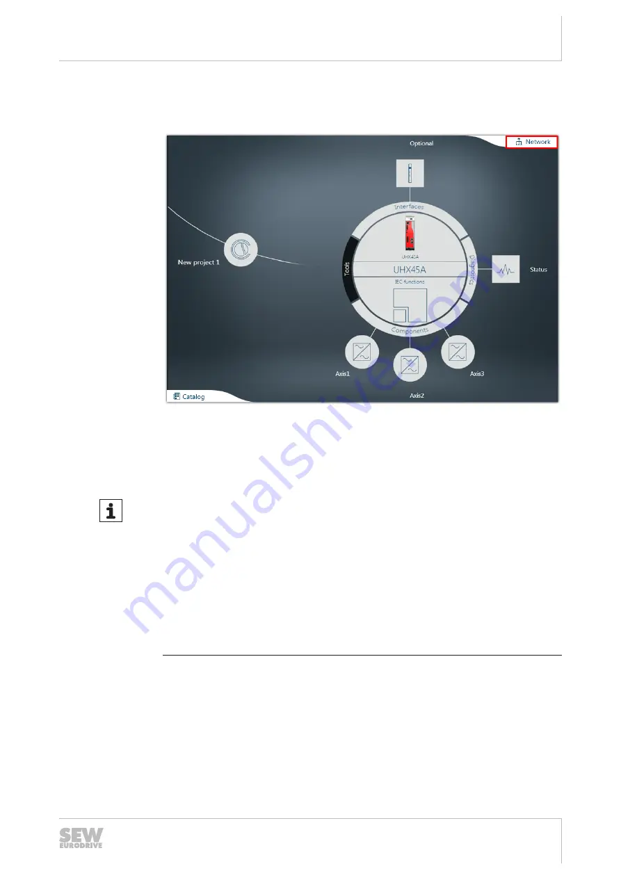
ð
The function view has 2 views. The tree view shows an overview of the entire
project. The circle view shows the current node as a large circle in the center of
the working area.
22807235723
3. To switch between the MOVISUITE
®
views, click the "Network" tab.
4. Enter a name for the MOVI‑C
®
CONTROLLER. The device is shown in the
MOVISUITE
®
project under this name.
INFORMATION
In order for the MOVI‑C
®
CONTROLLER device name to be both PROFINET- and
IEC61131‑compliant, SEW‑EURODRIVE recommends using a name that starts with
a letter and does
not
contain any spaces or control characters (hyphen, underscore,
period, colon, comma, slash, backslash).
When the MOVISUITE
®
project is imported into IEC Editor and TIA Portal, both tools
convert the name of the MOVI‑C
®
CONTROLLER according to their own internal al-
gorithms. A name according to the naming conventions ensures that the
MOVI‑C
®
CONTROLLER appears under the same name in the different tools.
If a name according to the naming conventions is not possible, select a
PROFINET‑compliant name. In this case, the IEC61131 compliance is automatically
created by MOVISUITE
®
.
24777730/EN – 01/2018


