background image

SERVOTOUGH SpectraScan User Manual 


02400001A/1 

19 


3.4.4 

Electrical Safety 

The Servomex SpectraScan Gas Analyzer is powered by voltages that could pose a hazard to the 
user.  Before any maintenance work is performed, disconnect power from the analyzer and turn off 
the gas supply.  Follow standard electrical safe work practices to prevent injuries. 


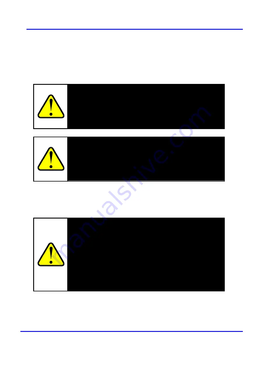
WARNING 


Electrical Hazard, Personal Injury and Equipment Damage: 

Do NOT 

perform maintenance on an energized or gas supplied analyzer. When 

performing maintenance on the unit, it is necessary to disconnect the power 
source from the unit, and turn off the gas supply lines (sample gas and zero 

gas). 


WARNING 


SYSTEM SAFETY: 

This analyzer is typed as permanently connected 

equipment and as such, must include a switch or circuit–breaker in the 

installation.  This switch must be supplied and installed by the customer (not 

provided by Servomex) must be suitably located and easily reached, and must 

be marked as the disconnecting device for the equipment. 


3.4.5 

Electrostatic Discharge 


WARNING 


Electrical Hazard, Personal Injury and Equipment Damage: 

The control of 

ESD is critical when performing maintenance on the Servomex SpectraScan 

Gas Analyzer.  To control ESD, users should wear ESD wrist straps and other 

grounding equipment between the analyzer and the skin. The wrist straps 

should be tested for ground continuity often.  Also, ground the analyzer 

(through the frame chassis or the control rack) to protect against: 


Damage to sensitive electronic components, such as circuit boards 


Electrostatic discharge 


User injuries from electrical shock when contact is made with the 
energized equipment. 


Summary of Contents for Servotough SpectraScan 2400

Page 1: ...Part Number 02400001A Revision 1 Language US English User Manual SERVOTOUGH SpectraScan 2400 Gas Analyzer PROCESS ANALYZERS...

Page 2: ...isive LLC of Boston MA USA who assume responsibility for the product performance with regard to software and set up using appropriate gas mixtures for calibration The methodology is patent protected a...

Page 3: ...ical Safety 19 3 4 5 Electrostatic Discharge 19 3 4 6 Ergonomic Considerations 20 4 UNPACKING THE ANALYZER 21 4 0 Component List 21 4 1 Removing the Analyzer from the Shipping Container 22 4 2 Inspect...

Page 4: ...7 0 6 Procedure for Connecting the Sample Lines 54 7 1 Enclosure Purge Connections 55 7 1 1 Purging of Enclosure Compartment 55 8 INSTALLATION CHECKLIST 57 9 VERIFICATION 59 9 0 Procedure 59 9 0 1 Set...

Page 5: ...ac 38 Figure 10 Connecting the Ethernet TCP IP communication cable 40 Figure 11 Location of the serial number tag 42 Figure 12 Location of debug RS 232 connector on MPU 44 Figure 13 Sample session in...

Page 6: ...nalyzer 26 Table 4 Wire Types 35 Table 5 SpectraScan Modbus register 48 Table 6 Diagnostic LED Indications 59 Table 7 Troubleshooting 67 Table 8 Measurement Specifications 69 Table 9 Physical Specific...

Page 7: ...SERVOTOUGH SpectraScan User Manual 02400001A 1 v This page intentionally left blank...

Page 8: ...st ensures all the required tasks are performed The verification test confirms span accuracy upon installation and includes the zeroing procedure which may be repeated periodically Short maintenance a...

Page 9: ...rmation is highlighted in this manual as WARNINGS and CAUTIONS and NOTES which are used as follows WARNING Warnings highlight specific hazards which if not taken into account may result in personal in...

Page 10: ...n hot surface ISO 3684 No 6043 Equipotentiality IEC 60417 No 5021 Frame or Chassis Terminal IEC 6041 No 5020 Double or Reinforced Insulation IEC 6041 No 5172 3 Direct Current IEC 60417 No 5031 Alterna...

Page 11: ...s and blending monitoring Catalysis and combustion process monitoring 2 1 Measurement Principle When a gas sample is introduced in the gas cell the light radiation provided by a broadband light source...

Page 12: ...SERVOTOUGH SpectraScan User Manual 02400001A 1 10...

Page 13: ...SERVOTOUGH SpectraScan User Manual 02400001A 1 11 This page intentionally left blank...

Page 14: ...tion and maintenance of this analyzer Servomex SpectraScan users must observe all prescribed safety guidelines and adopt good general work practices to adequately protect themselves fellow workers and...

Page 15: ...ed and grounded All cables entering the analyzer 24 VDC or 120 240 VAC power and communication must be separately jacketed as they enter the analyzer to prevent mis wiring symbol for ground USING THE...

Page 16: ...present in the cable and in the analyzer whenever a power cord is connected USE PROPER FITTINGS AND TIGHTENING PROCEDURES All connection fittings must be consistent with Servomex SpectraScan Gas Anal...

Page 17: ...table 1 conduit connector must be used that will not compromise the existing IP Rating 3 1 WARNINGS AND CAUTIONS This apparatus is suitable for use in Hazardous Locations as defined in Table 2 Hazardo...

Page 18: ...e area is known to be free of ignitable concentrations of flammable gases or vapours WARNING EXPLOSION HAZARD Substitution of components may impair suitability for class 1 division 2 and class 1 zone...

Page 19: ...traScan is designed to be safe The following hazards are unavoidably present when operating or servicing the Servomex SpectraScan Gas Analyzer All personnel connected to the operation installation or...

Page 20: ...w on either the intake or the exhaust side may cause the gas cell to over pressurize causing damage to the analyzer Care should be taken to remove any port caps or other flow barriers before connectin...

Page 21: ...ipment and as such must include a switch or circuit breaker in the installation This switch must be supplied and installed by the customer not provided by Servomex must be suitably located and easily...

Page 22: ...cal circumstances of operating or servicing the analyzer Ergonomic hazards of the Servomex SpectraScan Gas Analyzer include Lifting the analyzer Stretching or maintaining an awkward position WARNING P...

Page 23: ...2400001A 1 21 4 UNPACKING THE ANALYZER 4 0 Component List A standard Servomex SpectraScan Gas Analyzer is delivered with the following components Servomex SpectraScan Gas Analyzer unit Installation Ma...

Page 24: ...the cardboard shipping box and fold them out of the way 2 Lift the unit together with the inner packaging materials keeping the shock absorbing foam pieces around the unit 3 Set the unit with the inne...

Page 25: ...5 0 Environmental Requirements The following considerations are described in this section Dimensions Weight and Ventilation Operating Temperature Humidity and Pressure Combustion Hazard Power Require...

Page 26: ...roper installation can result in serious personal injury Make sure that the mounting structure can support a redundant weight factor four times the total weight of the analyzer If not reinforce the st...

Page 27: ...ide range of ambient temperature and humidity as shown in Table 14 Environmental Specifications on page 72 The analyzer should be operated in a non condensing environment to avoid condensation on the...

Page 28: ...outgoing sample lines are provided in Section 7 SAMPLE GAS CONNECTIONS on page 49 Other fitting sizes and styles are available from Servomex to be installed on the inlet and exhaust ports as a special...

Page 29: ...Servomex SpectraScan Gas Analyzer must be mounted with eight 3 8 16 x 1 UNC bolts and matching lock washers and nuts 2 Consider the order of installation mount the analyzer onto the mounting surface...

Page 30: ...SERVOTOUGH SpectraScan User Manual 02400001A 1 28 This page intentionally left blank...

Page 31: ...tching lock washers and nuts WARNING Personal Injury or Death Wiring of the analyzer must be in accordance with local regulations Emissions Class A Equipment used in establishments other than domestic...

Page 32: ...nce for safe operation The Red Circle in the figure above identifies the conduit fitting through which the power communication and external stream switching solenoid valve cables are to be connected T...

Page 33: ...SERVOTOUGH SpectraScan User Manual 02400001A 1 31 Figure 4 Analyzer with Cover Open...

Page 34: ...SERVOTOUGH SpectraScan User Manual 02400001A 1 32 6 0 1 Component Layout Figure 5 Interior of the Servomex SpectraScan Gas Analyzer NOTE See Figure 6 for detail of SpectraScan internal components...

Page 35: ...tional Power Cable Purge Port Purge Port Conduit Sample Inlet Sample Exhaust Enclosure Lid Display Cable Enclosure Fuse Spare Fuses Plate Motor Assembly TCP IP Jack Circuit Board Heater Wires TCP IP C...

Page 36: ...d and installed by the customer not provided by Servomex must be suitably located and easily reached and must be marked as the disconnecting device for the equipment WARNING Electrical Shock and Equip...

Page 37: ...tion or for 120 240 VAC operation must use a 3 conductor cable The ground wire in this 3 conductor cable must be electrically connected to the earth ground lug in the analyzer Connection Wire type Pow...

Page 38: ...SERVOTOUGH SpectraScan User Manual 02400001A 1 36 6 2 1 Power Wiring 24 VDC Figure 8 Wiring the SpectraScan with 24 VDC...

Page 39: ...n of the cable to the anchor point provided inside the enclosure using a cable tie Be sure to leave enough slack in the cable so the red and black wires reach the power terminal block on the main boar...

Page 40: ...SERVOTOUGH SpectraScan User Manual 02400001A 1 38 6 2 2 Power Wiring 120 240 VAC Figure 9 Wiring the SpectraScan with 120 240Vac...

Page 41: ...on the AC Power Module 4 Strip 10mm 0 4 of insulation from the line black neutral white and ground green leads of the cable 5 Connect Earth Ground a The terminal tabs on the AC Power Module have three...

Page 42: ...SERVOTOUGH SpectraScan User Manual 02400001A 1 40 6 3 Communication Connection Figure 10 Connecting the Ethernet TCP IP communication cable...

Page 43: ...e connected 2 Open the cover of the SpectraScan using a large flat headed screwdriver turn the latch turn counter clockwise and open the cover 3 Bring the communication cable into the enclosure throug...

Page 44: ...a request for an IP address via DHCP The DHCP server will answer the request and provide an IP address to the instrument The instrument will remember that IP address for as long as it remains powered...

Page 45: ...mers prefer to assign a static IP address to their instruments Assigning a static IP address requires that you have physical access to the system board Connecting to the system board via RS 232 requir...

Page 46: ...inal program start a terminal session to the MPU Hit return a few times and you will get a command prompt from the MPU The command prompt is 6 At the command prompt type the command ip config followed...

Page 47: ...rectly choose reboot The system will then store the new IP configuration data shut down and then restart 14 The system requires roughly 1 minute to reboot Once the system has rebooted you will be pres...

Page 48: ...only a point to point link Do not bridge the receive and transmit pairs the instrument cannot be used in multi drop bus configurations Connecting the instrument s RS 422 port to an external RS 422 dev...

Page 49: ...dividual push down connectors as shown in the figure NOTE Although the board label says RS 485 this port will not function in multi drop bus mode It will only work as a point to point link with a 4 wi...

Page 50: ...Modbus The instrument acts as a Modbus server the external controller is the client Modbus runs either over RS 422 or Ethernet interfaces The instrument is configured in the following way Modbus prot...

Page 51: ...es may vary depending on application Figure 16 Typical Gas Connection Configuration NO NC 10 Micron Particulate Filter Pressure Relief Mechanism Sample Gas Solenoid Zero Gas Solenoid Manual Valve Manu...

Page 52: ...port caps or other flow barriers before connecting any sample line or switching on the analyzer Also make sure the exhaust routing is appropriate for your specific application CAUTION Equipment Damag...

Page 53: ...CAUTION Equipment Damage Restricting the gas flow on either the intake or the exhaust side may cause the gas cell to over pressurize Care should be taken to remove any port caps or other flow barrier...

Page 54: ...ult the first two relays are used for automatic zeroing upon initiating a software zero command the relays energize providing 24 VDC power to external solenoid valves Upon completion of the zeroing pr...

Page 55: ...ly open respectively Solenoid lines 1 2 3 and 4 should be connected to the rightmost connector bank on the front edge of the PCB to connector ports SOL1 GND SOL2 and GND respectively as shown in the d...

Page 56: ...and exhaust lines to the Servomex SpectraScan sample inlet and exhaust ports 8 Ensure proper sample gas and zero gas temperature and conditioning In general sample conditioning is application dependen...

Page 57: ...the ports using male NPTF connectors or use fittings to adapt the purge ports on the analyzer to the connectors on the gas purge lines One purge port on the analyzer acting as an inlet should be conne...

Page 58: ...SERVOTOUGH SpectraScan User Manual 02400001A 1 56 This page intentionally left blank...

Page 59: ...an Gas Analyzer from shipping crate and inspected for damage 3 Chose appropriate mounting space and structure considering all Environmental Requirements beginning on page 23 4 Mounted the analyzer sec...

Page 60: ...SERVOTOUGH SpectraScan User Manual 02400001A 1 58 This page intentionally left blank...

Page 61: ...he Servomex SpectraScan Gas Analyzer is sufficiently warmed up Warm up The unit s interior is temperature controlled and will only meet measurement accuracy specifications when sufficient time is allo...

Page 62: ...urn off the zero gas and turn on the sample gas either through software in the case of automated sample switching configuration or manually 3 Start collecting data 4 Wait until data values from the an...

Page 63: ...ysical intervention Typically every 18 months the spectrometer light source needs to be replaced Recommended maintenance and operation verification of the Servomex SpectraScan Gas Analyzer consists of...

Page 64: ...d to the light source prior to inserting it into the cell WARNING Electrical Hazard Personal Injury and Equipment Damage Do not perform maintenance on an energized or gas supplied analyzer When perfor...

Page 65: ...osen and remove the four bolts and four lock washers at the corners of the light source circuit board Lift the blue light source circuit board up and out of its mounting hole This circuit board with t...

Page 66: ...21 Mounting Hole for Light Source 9 Replace the four bolts and four lock washers to secure the circuit board to the sensor head Tighten the bolts in a cross pattern 10 Replace the connector back into...

Page 67: ...65 13 Turn on power and gas supply 14 Wait for at least 30 minutes and until the cell temperature stabilizes at the set operating temperature indicated by the green Run light on the display 15 Perfor...

Page 68: ...SERVOTOUGH SpectraScan User Manual 02400001A 1 66 This page intentionally left blank...

Page 69: ...ation at the operating temperature Negative concentration reading Zeroing on sample gases or insufficient purging prior to zeroing Excessive drift Analyzer has not fully warmed up or sensor head tempe...

Page 70: ...SERVOTOUGH SpectraScan User Manual 02400001A 1 68 This page intentionally left blank...

Page 71: ...ent Specifications Measurement Technique Light absorption spectroscopy Gas Cell Volume Path Length 100 mL 35 cm Zero Drift 0 2 of full scale FS per month typical Intrinsic Error Accuracy 1 FS typical...

Page 72: ...tion Wall Mounted See Dimensions Weight and Ventilation on page 24 for installation considerations Vibration Immunity Resistant to low amplitude vibration Table 9 Physical Specifications 12 2Communica...

Page 73: ...le Temperature and Humidity 0 to 50 C 32 to 122 F standard 5 to 95 rH non condensing Contact Servomex for higher temperature requirement Material Of Wetted Parts Nickel plated or anodized aluminium ga...

Page 74: ...mental Specifications Ambient Operating Temperature Humidity Range 20 to 50 C 4 to 122 F 5 95 rH non condensing System Cooling None required Storage Shipping Temperature Humidity Range 20 to 60 C 4 to...

Page 75: ...9 measurement principle 9 power AC 38 DC 36 power rating 72 power rating label 34 power requirements 26 34 52 72 pressure allowable gas cell 71 purging 55 regulation 12 sample cleanliness 51 ports 51...

Page 76: ...d Jarvis Brook Crowborough East Sussex TN6 3FB United Kingdom TEL 44 0 1892 652181 Fax 44 0 1892 662253 www servomex com NOTE All analyzers returned to Servomex or one of its appointed agents for serv...

Reviews: