


INSTALLATION AND OPERATION INSTRUCTIONS — PERSONAL ALARM SYSTEM
20
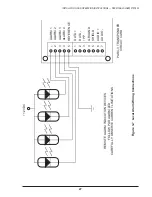
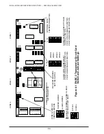
ALIGN TEMPLATE HOLES
WITH BOX HOLES
MARK BOTH RIGHT AND LEFT SIDES OF THE BOX BY ALIGNING TEMPLATE TO
EACH PAIR OF BOX HOLES.
STRIP BACKING PAPER FROM SELF-ADHESIVE MAGNETS AND CENTER
THEM AT MARKED LOCATIONS.
MARKING
TEMPLATE
1/2"
MARK MAGNET LOCATION
ALONG EITHER SIDE OF TEMPLATE
1/2" DOWN FROM MOUNTING SURFACE
1" DOWN FOR 03RM/IV
(1" for
03RM/IV)
Figure 3-2 Magnet Position for Tamper Switch Activation
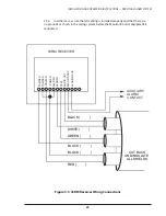
3.2.3
Wiring connections are via a 10-position plug-in connector. Attach the
connector to the wiring before plugging connector into circuit board. The wiring must
be attached to the connector in accordance with Figure 3-3. Figure 3-3 shows wire
colors for the type of wire normally used. If the colors of your cable are different,
change the wire colors listed on Figure 3-3 and retain as your as-built information.
A blank space is provided for this purpose.
3.2.4
Pay particular attention to the shield wires at this end. The shields are not to be
connected but must be isolated from other wires or grounds. Trim shields short and
apply electrical tape to insulate.


