


29
INSTALLATION AND OPERATION INSTRUCTIONS — PERSONAL ALARM SYSTEM
4.0
INITIAL SET-UP AND ADJUSTMENT
4.1
General
4.1.1
This section assumes that you have successfully completed the equipment
installation and all hardware has been installed at the job site.
4.1.2
If you have set up the system on the bench for testing and adjustment before
going to the field, you will also be at this point.
4.1.3
In this section you will set the addresses of each PARC-3 and verify that all
jumpers are installed in the correct locations. The addresses of the MX-2000 or DCU are
set at the factory, so you will be setting the PARC-3 addresses to match those of the
MX-2000 or DCU.
4.2
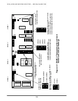
Setting Transponder and Receiver Addresses
4.2.1
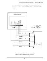
Data communications take place between the central control point (MX-2000
OR DCU) and each of the Receiver/ Communicator (PARC-3) units. Each PARC-3 on a
data bus is assigned one of the ten available unique receiver and transponder address
sets. In the same way, the MX-2000 or the Data Collection Unit has one receiver
address and one transponder address for each PARC-3 on the system. For example,
a PARC-3 is capable of four zones, so a 40-zone central unit (MX-2040) can address 10
PARC-3 units and contains one set of receive and transmit addresses for each. The MX-
2040 is microprocessor controlled, and all the receiver and transponder addresses are
contained in software. There are no switches inside the MX-2000 similar to those you
will see on each PARC-3.
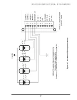
4.2.2
The system communicates with each of the PARC-3’s by sending a digital
message in which the first part of the message contains the address of the intended
PARC-3. The transponder address is defined by setting one set of 8 switches contained
on one DIP circuit board package. The receiver address is set the same way with a
separate set of 8 switches.
4.2.3
You will recall from the Theory of Operation that the PARC-3 transponder
system further operates on a “loop” with up to 10 PARC-3’s connected on each line.
Since each PARC-3 (transponder) contains 4 zones, it follows that there are 40 zones
contained on one transponder “loop.”
4.2.4
The MX-2000 can support up to three “loops” of PARC-3’s, or a total of 120
alarm zones. The Data Collection Unit (DCU) is capable of one loop of up to 40 alarm
zones.


