


11
INSTALLATION AND OPERATION INSTRUCTIONS — PERSONAL ALARM SYSTEM
2.3
Receiver (03RM)
2.3.1
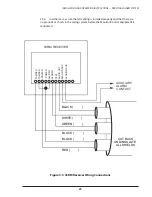
The transmitted ultrasonic frequencies are received by the ceiling or wall-
mounted 03RM receiver units. The 03RM is designed for mounting in a double-gang
electrical box using the tamper resistant screws provided.
2.3.2
Each 03RM contains an ultrasonic frequency receiving element and an audio
frequency microphone. Figure 2-2 shows the 03RM block diagram. The 03RM receives
ultrasonic alarm signals, amplifies them, and determines if they match the unique
frequency and modulation pattern generated by the PAS transmitter. If the alarm
signal is present, the red LED on the front panel lights and a relay contact communi-
cates the alarm condition to the PARC-3 (Receiver/Communicator). The microphone
receives the sounds in the immediate area. These signals are also amplified and sent to
to the PARC-3 for processing. An optional video output provides real-time video
verification of active alarms (03RM/IV).
M
ULTRASONIC
TRANSDUCER
MICROPHONE
DECODER
TAMPER
LED
AUDIO
TO
PARC-3
+12 VDC TEST
INPUT
OUTPUT
LOGIC
REF.
FREQ#1
REF.
FREQ#2
POWER
REG.
+12 VDC
RETURN
AMP.
AMP.
AMP.
AMP.
ALARM
RELAY
AUX.
RELAY
LEVEL
ADJ.
RANGE
ADJ.
(SHOWN ENERGIZED)
TEST SIGNAL
OSCILLATOR
Figure 2-2 Personal Alarm Receiver (03RM)


