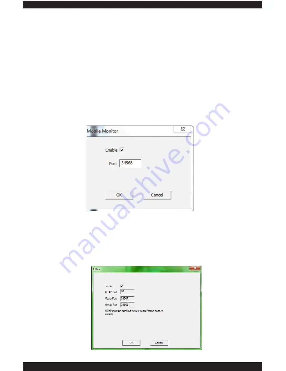
background image

UPNP 

The 

UPNP 

is used to enable universal plug and play for Point-to-Point remote 

access. Enabling the UPNP will automatic detect the HTTP port (80), Media 

port detection (34567) and mobile port detection (34568). These features 

must also be enabling on your local router to take affect for our Point-to-Point 

remote access service to work without having to open ports from your router.  

See IPcam-SD quick start guide for additional information on Point-to-Point 

remote access. Click OK to confirm set up or click CANCEL to cancel.

106

2) Go to the second computer with CMS software installed.  Access the 

NetService of the IP camera and chose NTP.  Input the IP address of computer 

#1 above into the “Server IP” section, leave the Port 123 (default), select the 

Time Zone according to your area (for example: California we select “GMT 

-8:00” for the time zone),  and setup an update period (system default is set to 

10 minutes).  Click OK to accept the setting or CANCEL to cancel.

ARSP

 (not applicable with IP camera model)

MOBILE MONITOR

The 

MOBILE MONITOR

 service allows you to enable (default, checked) or 

disable (unchecked) mobile monitoring and also specify the port number 

that you wish to use. Double click on this option to bring up its corresponding 

configuration window as shown below. Place a check mark in the box to enable 

mobile monitoring and then input the port number; the default port is 34568 

for mobile monitoring service, recommended. Mobile monitoring has to be 

enabled for any SmartPhone such as iPhone, iTouch, iPad, blackberry, windows 

mobile, and android to remote access using the free App provided.

Summary of Contents for ClockCam-WiFi

Page 1: ...CLOCKCAM WIFI User s Manual Wall Clock iSecurity Camera with Micro SD Recorder 12 6 9 3...

Page 2: ...ust the product or put it in another place Extend the distance between the equipment interfered and the product Refer to dealers or experienced radio electrician for help Warranty SecurityMan Inc warr...

Page 3: ...t Schedule Type Selector Plan Template Window Schedule View Version Info IPCAM CMS Account Group Add Group Delete Group Group List Group Rights List User User Account Window Add User Delete User Modif...

Page 4: ...l Time Streaming Protocol Cloud GUI Display CAM Name Anti Jitter Transparency Area Masking Date Time Stamp Camera Name Position Mirror Image Flip Image Anti Flicker IRSwap Advanced SD Card Manage Read...

Page 5: ...mpression for smoother video streaming and smaller file size 2 in 1 Design Wired Ethernet or Wireless Wi Fi Multiple private recording options motion detection manual or schedule recording to SD or re...

Page 6: ...e to medical equipment 1 This product may cause medical equipment to malfunction 2 Place the product at least 22cm from the heart pacemaker Radio waves can potentially influence the pacemaker and can...

Page 7: ...temperature or humidity may change rapidly Keep it dry dustless and avoid lens exposure in direct sunlight Keep product away from heat sources such as electric heaters Do not use the camera near harm...

Page 8: ...etwork Dongle Quick Start Guide Mounting Screw 2 x Warning Stickers Ethernet cable Power adapter www securitymaninc com VIDEO AUDIO MONITORING AND RECORDING DEVICES IN USE ON THESE PREMISES SecurityMa...

Page 9: ...wer Socket NOTE The reset button located on your camera is used to reset the IP camera to its original factory default settings To apply power up your camera then press and hold in the reset button us...

Page 10: ...rt a Micro SD card not included into the Micro SD slot 3 Using the Ethernet cable provided connect one end into the Ethernet port of the clock and the other into your router switch 4 Insert the male e...

Page 11: ...u select Login your camera screen will be displayed immediately 2 Begin by opening Internet Explorer and going to http www xmeye net fig 1 1 Select Register and input your information into the availab...

Page 12: ...the serial ID of the IP camera which you can obtain by scanning the QR Code located on the device please refer to the QSG for instructions on how to scan the QR Code Provide a Device Name for your de...

Page 13: ...This method is used to add your IPCam without registering your user information There are numerous ways to add view your IP camera under By Device QR Code Search in LAN and Address 2 Serial QR Code Pl...

Page 14: ...he four quadrants B Play Stop Icon Record Icon Delete Channel Icon Alarm Icon Snapshot Icon Microphone Icon C IPCam Live App Settings Icon Gives you access to change the settings for the IPCam Live ap...

Page 15: ...ble for IP camera G Close Far You can zoom up to a specific section of the camera Not applicable for IP camera H Aperture Configure the opening of a lens s diaphragm through which light passes Not app...

Page 16: ...Video Setting Changes the quality of the video resolution frames per second bitrate etc 6 SD Card Info Displays information on the SD card Formats the SD Card and configures the overwrite function 7 A...

Page 17: ...ved onto the SD card in the IP camera You may select through the date time and type of recorded files i e Motion recording snapshots video blind etc You can view the IP camera snapshots which were tak...

Page 18: ...Help Configures the settings for the IPCam application on your phone Configurations include alert sounds audio video ratio wifi network etc Information on the IPCam application and contact informatio...

Page 19: ...ge with noticed 3 The CMS Central Management Software Setup screen will appear as shown below Select Yes in the User Account Control window and then click Next to continue or Cancel to cancel the inst...

Page 20: ...installing the CMS to your computer recommended as illustrated above 7 Click Next in the Ready to Install window and then click Finish to complete the CMS software installation as shown below NOTE Wh...

Page 21: ...ow will appear as shown below click on OK to continue NOTE The default User Name is super password leave blank 2 At the CMS main screen click on System and then Add Remove IPCam to open the device man...

Page 22: ...add the device and close out any open windows till you get tot he live view screen In EditDevice window please modify the default IP Address Ethernet Subnet Mask and Gateway to match your local area...

Page 23: ...tination folder Next select the Record Setting and make sure Overwrite is checked and then select the disk partition you want save the video picture files as illustrated below Click Apply or OK to con...

Page 24: ...era s selected from the Device Display Area C Horizontal Expand Clicking on the HORIZONTAL EXPAND will hide the device display area giving you a wider look at the live feed from your camera D Multi Sc...

Page 25: ...els Audio Enables Disables sound for the selected channel Local Record Starts manual recording for the selected channel all recordings are stored to the local computer Check System PC Config for local...

Page 26: ...s such as PTZ Controls Color Adjustment Playback and CMS configuration and Playback The menu area consists of the following NOTE The area above the MENU area will change to correspond with options tha...

Page 27: ...rows The NAVIGATIONAL ARROWS allow you to move your camera in the corresponding direction when you click them giving you a full 360 degree horizontal motion and 120 degree vertical motion for pan and...

Page 28: ...ging the position of the camera To add a preset point first move the IPcam SD to the desired location choose the Preset number and click the to add it or use the icon to delete it To pan to preset pos...

Page 29: ...d to adjust the cameras brightness level B Contrast The CONTRAST adjustment bar is used to adjust the cameras contrast level C Saturation The SATURATION adjustment bar is used to adjust the cameras sa...

Page 30: ...ce screen located on the bottom right hand corner of the screen Once selected the the system control screen will pop up providing you with the following options A PC Config consists of basic CMS netwo...

Page 31: ...to click the APPLY button located at the bottom of each tab to save your changes and click on the X located at the top right corner of the screen exit A Base Config CMS recording configuration B Alar...

Page 32: ...record and operate These categories are A Log Maintenance IP camera alarm log configuration B Snapshot snapshot file path and format settings C Local Record event recording file path configuration D D...

Page 33: ...ng its contents Save alarm log consists of 7 15 and 30 default days to save the log files SHOW ALARM LOG The SHOW ALARM LOG option allows you to enable default disable the real time alarm events that...

Page 34: ...n your computer that you would like to store the snapshots that are taken To use this feature simply click on the BROWSE button located to the right of the current destination description to make your...

Page 35: ...corded events to RECORD DIRECTORY The RECORD DIRECTORY feature allows you to specify the location on your computer that you would like to store the recorded events To use this feature simply click on...

Page 36: ...st if you have more than 2 IP cameras listed in the same zone the default setting is unchecked SINGLE SCREEN MAIN STREAM MULTI SCREEN EXTRA STREAM The SINGLE SCREEN MAIN STREAM MULTI SCREEN EXTRA STRE...

Page 37: ...d on the Base Config tab allows you to specify how often the CMS should update its date time by synchronizing with your computer date and time The options available are Never default Everyday Every So...

Page 38: ...uired Before Exiting Auto Login START UP The START UP area located on the Basic Config tab consists of 7 settings that are used to configure the actions to be taken every time both the computer and th...

Page 39: ...ITH THE LAST MONITORING CHANNEL feature allows the CMS software to automatically start up with displaying the same live feed s that were being monitored when the CMS was shut down close exit The syste...

Page 40: ...Trigger used configure alarm Input Output related features B Video Motion used configure Motion Detection alarm features C Video Blind used configure Video Camera Blind alarm features D Device Discon...

Page 41: ...r of the screen exit A Device List used to select which device you want to configure B Camera Mapping camera to I O mapping Map the IPcam SD right side to the Alarm Input Mapping left side by selectin...

Page 42: ...ure simply click on the BROWSE button located to the right of the current destination description to make your selection FULL CH DISPLAY The FULL CH DISPLAY check box will allow the CMS to display the...

Page 43: ...39...

Page 44: ...the CMS to monitor video motion alerts C Alam Sound enables disables audible alert notification D Sound File Path used to specify the location of the sound file you want to use E Full CH Display enab...

Page 45: ...that can be heard from your computer whenever an alarm is triggered SOUND FILE PATH The SOUND FILE PATH feature allows you to specify the location on your computer of the audible alert tone that you w...

Page 46: ...remember to click the APPLY button located at the bottom of each tab to save your changes and click on the X located at the top right corner of the screen exit A Device List used to select which devic...

Page 47: ...nd is enabled and an event occurs the system will only record video footages no picture snapshots will be taken ALARM SOUND The ALARM SOUND enables disables the audible alert that can be heard from yo...

Page 48: ...you want to use NOTE Please remember to click the APPLY button located at the bottom of each tab to save your changes and click on the X located at the top right corner of the screen exit DEVICE LIST...

Page 49: ...that will allow you to program the CMS to set overwrite option recording file length alarm file length select storage disks record on specific days times and event types These categories are A Basic...

Page 50: ...will be stored in a folder called Record under the selected storage drive or DISK LIST below DISK LIST The DISK LIST area displays all the partitions hard drives that are available for you to select a...

Page 51: ...amera should record and the type of recording that should be implemented during the set schedule Regular Detect Alarm thus saving space and the amount of unwanted recordings that would be generated du...

Page 52: ...e Record Setting tab lets you edit any of the pre configured plan templates and even create a new one based on your requirements To begin click on the Edit Template button using your mouse to bring up...

Page 53: ...ime frame D Detect enables motion detection for the set period time frame E Alarm enables alarm activated recording for the set period time frame F Plan Template Window displays all templates that hav...

Page 54: ...LIST inside the Record folder under the sub folder MotionRecord ie C Record MotionRecord folder NOTE The Detect scheduled recording are accountable for Video Blind recording All video blind event rec...

Page 55: ...the Plan Template Window and click the Delete button to delete it SCHEDULE VIEW The SCHEDULE VIEW area is used as a visual map of the CMS s current recording schedule VERSION INFO The Version Info or...

Page 56: ...sers with CMS Account rights can add create or modify these settings The 2 tabs located on the CMS Account window are NOTE The IP Cam CMS Account settings only pertain to users who are able to access...

Page 57: ...at will let you create user groups with specific rights privileges that can be applied to newly created users These options are A Group List displays all the groups available B Add Group used to creat...

Page 58: ...ll be prompted to provide a name and description of the new group when selected DELETE GROUP The DELETE GROUP button allows you delete any of the groups that you no longer need NOTE The Administration...

Page 59: ...nd features RECORD SETTING The RECORD SETTING right allows users to create and change scheduled recording settings IPCAM CONFIG The IPCAM CONFIG right gives users access to the IP camera configuration...

Page 60: ...WINDOW The USER ACCOUNT WINDOW displays all the all the users that have been created under different groups or rights ADD USER The ADD USER button allows you to create new CMS user accounts To create...

Page 61: ...confirm or CANCEL to cancel NOTE The Super user account is created by default and cannot be deleted nor modified The system default password is blank for Super account MODIFY PW The MODIFY PW modify...

Page 62: ...s you to choose the event type to look in B Operation Alarm drop down allows you to select a specific event type to look for C Begin Time used to specify a specific start date time to search between D...

Page 63: ...to display the calendar To adjust the time click the value you wish to change and click on the up down arrows to increase or decrease its value when highlighted END TIME The END TIME drop down menus a...

Page 64: ...p to the next page in the event log For example the event log detail screen will only display 34 events per page therefore in order to get to the next page you would have to click on the NEXT PAGE but...

Page 65: ...isplays all the cameras that have been added to the CMS 2 Add Area used to add an area 3 Add Device used to add a IP camera 4 Modify used to modify area a camera connection settings 5 Delete deletes d...

Page 66: ...igure or add a device to ADD AREA The ADD AREA option will allow you to join your IP camera into groups to help keep your security system organized For example you can create a group called HOME and a...

Page 67: ...P Search initiates the find device feature C Device Name allows you to manually name your IP camera D Login Type used to specify the cameras login protocol E IP Address cameras identification number t...

Page 68: ...the IP address that you have assigned for the IP camera when installing the CMS software on a device outside your network since using the IP SEARCH feature will be unable to locate your camera outside...

Page 69: ...sword and Zone to comply as instructed above NOTE When using serial ID for Cloud it is not required to open ports from you router however UPnP is required to be enabled in your local router EDIT DEVIC...

Page 70: ...u are unsure as to what IP address Subnet Mask and Gateway to use or reference our QSG Quick Start Guide to obtain an IP address ADD DEVICE The ADD DEVICE option adds the selected configured device to...

Page 71: ...67 Next make sure your IP camera is connected to your network and turned on Select the area you created HOME and click on the ADD DEVICE option to bring up the EDIT window as shown...

Page 72: ...search for your camera and display it in the device list window as shown in the image below Using your mouse click on the IP Address that represents your IP camera and click on the ADD DEVICE button...

Page 73: ...69 Click OK to close the EDIT window and click ok once more to close the Add Remove IP Camera window as illustrated...

Page 74: ...ired profile name and then click on the delete icon IMPORT CONFIG The IMPORT CONFIG option allows you to restore the saved bin profile settings back to the CMS software To import CMS configuration sim...

Page 75: ...will operate and be controlled The IPCam Config section consists of the following sections 1 Device List displays all the devices that are controlled by the CMS 2 Sub Menu Icons displays all the sub...

Page 76: ...can be configured through the CMS NOTE You will be prompted to select a device from the device list in order to view the IPCam Config options SUB MENU ICONS The SUB MENU ICONS area displays all the su...

Page 77: ...options include 1 Record Playback Used to set up the IP cameras video and photo recording parameters 2 Alarm Used to set up the IP cameras alarm parameters 3 System Used to configure the IP cameras n...

Page 78: ...enu located in the IPCam Config settings allows you to configure the IP cameras video and snapshot recording parameters and consists of the following 2 sub menus 1 Video Video recording configuration...

Page 79: ...t which camera you want to configure B Recording Duration used to specify the length of each recording segment C Record Type used to implement a recording structure D Schedule Area used to setup a rec...

Page 80: ...hedule will not be taken into effect if there is a schedule set under the video motion settings Manual enables 24 hour video recording None disables manual recording SCHEDULE AREA The SCHEDULE AREA le...

Page 81: ...want to configure B PreSnap used to specify the amount of photos to be taken when an event occurs C Record Type used to implement a recording structure D Schedule Area used to setup a recording sched...

Page 82: ...lets you set up to 4 different recording periods for each day of the week By doing this you can create schedules that will allow you manipulate when the IP camera should start and stop taking snapshot...

Page 83: ...cording parameters and consists of the following 6 sub menus 1 Video Motion Motion detection configuration 2 Video Blind Video blind configuration 3 Alarm Input Alarm I O configuration 4 Alarm Output...

Page 84: ...l D Schedule used to setup a recording schedule E Action Area used to control what the IP camera should do when an event occurs F PTZ Activation enables motion activated tour and preset movement G Not...

Page 85: ...ay of the week By doing this you can create schedules that will allow you to schedule when the IP cameras should start and stop implementing motion detection recording thus saving space and the amount...

Page 86: ...ll be subtracted from the Pre Record time frame The system default setting is interval 1 second the earliest the system can start to record on an event To extend the event start time to record please...

Page 87: ...ection sensitivity level D Schedule used to setup a recording schedule E Action Area used to control what the IP camera should do when an event occurs F PTZ Activation enables motion activated tour an...

Page 88: ...e ACTION AREA lets you specify what the IP camera should do when a blind event occurs and consists of the following option Alarm Output enables the IP cameras alarm output device that is connected to...

Page 89: ...l recording will not stop until 5 00 35 pm 10 second default 15 second delay COPY The COPY button can be used to copy the current configuration on the screen to the other cameras available through the...

Page 90: ...ontrol what the IP camera should do when an event occurs E PTZ Activation enables alarm input activated tour and preset movement F Notification Area used to select how you want to be notified when an...

Page 91: ...SD card of the IP camera PTZ ACTIVATION The PTZ ACTIVAION button lets you select the tour preset that you would like to use whenever an alarm input occurs This feature also consists of a DELAY post mo...

Page 92: ...r its default 10 second per camera failure event recording has expired For example if a camera failure event occurs at 5 00 00 pm and you have the delay time set to 15 seconds the actual recording wil...

Page 93: ...ces that has higher power rating or self powered output devices may not be supported ON The ON check box enables the IP camera alarm output device to be active or stay on 24 7 This option will not be...

Page 94: ...ut saving the changes EVENT TYPE The EVENT TYPE drop down is used to select which monitoring function you wish to enable and consists of the following options SD Card Not Found sends an alert when the...

Page 95: ...ervice Network services configuration 5 GUI Display Camera configuration SHOW LOG The SHOW LOG option is used to enable checked and disable un checked monitoring events to be saved in the system log f...

Page 96: ...he IP cameras time format E Language used to set the IPcam SD s display language F HDD Full used to enable disable the overwrite feature of the SD card G Video Standard NTSC PAL video format Please us...

Page 97: ...s include 12 HOUR 24 HOUR LANGUAGE The LANGUAGE drop down lets you change the language of the IP cameras menu It is important that you stay away from making changes unless you are really sure that you...

Page 98: ...STANDARD to PAL European move your cursor over to the drop down arrow and left click it to display the options available DST The DST option allows you to set up the IP camera to automatically update...

Page 99: ...4 compression not configurable C Resolution resolution configuration D FPS frames per second configuration E Bit Rate Type Constant or Variable Bit Rate selection F Quality lets you define the quality...

Page 100: ...tage quality but takes less hard drive space and faster video streaming NOTE The FPS ranges from 1 30fps the system default setting for main stream is 30fps and the default for extra stream is set at...

Page 101: ...intervals per second VIDEO AUDIO The VIDEO AUDIO option is used to enable default checked and disable un checked audio or video for the selected stream type Main Extra NOTE The audio must be checked...

Page 102: ...ts you manually input the networks default gateway E Primary DNS used to input your networks primary DNS address F Secondary DNS used to input your networks secondary DNS address G Media Port lets you...

Page 103: ...isables the Dynamic Host Configuration Protocol which is a protocol used by a network server to dynamically assign IP addresses to networked devices We recommend that you assigned a local area network...

Page 104: ...y the port number that you have selected your router to use for the IP camera to be accessible over the internet The media default port is 34567 recommended port HTTP PORT The HTTP PORT edit box lets...

Page 105: ...rom NET CARD click on the Search button to start searching for the wifi access point s or SSID in your network Click to highlight or select the known access point and then check Enable box Next input...

Page 106: ...cessing the camera B DDNS used to set up your DDNS account information for remote access C Email used to enable disable email alert notifications D NTP used to enable network time protocol to update a...

Page 107: ...isted allowed or black listed disallowed from accessing the IP camera remotely Double click on this option to bring up its corresponding configuration window as shown below Make sure to check Enable b...

Page 108: ...k OK to confirm set up or click CANCEL to cancel EMAIL The EMAIL service allows you to enable checked or disable default unchecked email alert notifications Double click on this option to bring up its...

Page 109: ...computers one computer to enable NTP service and the second computer running CMS software 1 To enable NTP service on computer 1 or server PC go to Control panel Administrative Tools Services Scroll to...

Page 110: ...er IP section leave the Port 123 default select the Time Zone according to your area for example California we select GMT 8 00 for the time zone and setup an update period system default is set to 10...

Page 111: ...rovide a directory name starting with a forward slash Click OK to confirm set up or click CANCEL to cancel NOTE The directory Name path for FTP cannot be blank and it has to start with a forward slash...

Page 112: ...m connection and sdp is the command used in VLC player To connect using extra stream input value 1 instead of 0 NOTE Please noticed that the symbol is required in between all commands instructed above...

Page 113: ...s screen CANCEL The CANCEL button discards any changes made and exits back to the previous screen GUI DISPLAY The GUI DISPLAY sub menu located in the System menu option consists of 14 basic settings r...

Page 114: ...sition button located to the right of the CHN NAME caption to bring up the chn name edit box NOTE The maximum alphabets and numbers can be up to 20 characters long ANTI JITTER The ANTI JITTER feature...

Page 115: ...positioned anywhere on the screen by using the Position button IR SWAP The IR SWAP by default is unchecked Please check it in cases where the color of the images maybe degrading or fading away Checkin...

Page 116: ...tenance controls etc These options include 1 SD Card Manage SD card management 2 IPCam CMS Account IP camera user account configuration 3 Maintenance Auto maintenance configuration 4 Default Apply man...

Page 117: ...the changes DISPLAY WINDOW The DISPLAY WINDOW displays all the current partitions and types that are currently on the SD card being used in the IP camera The display windows consists of Index Disk Ev...

Page 118: ...will pop up to confirm the operation please click OK to confirm or CANCEL to cancel NOTE It is highly recommended that you always format a newly installed micro SD card to insure that it is formatted...

Page 119: ...y window displays all active user accounts B Modify User used to modify the selected users rights C Modify Group used to modify group rights D Modify PW used to modify the selected users password E Ad...

Page 120: ...dify the users rights and group To authorized certain users rights simply place a check mark on the number associated with the authority Uncheck the number next to the authority to disable the rights...

Page 121: ...se elect the user name you want to modify type in the old password type in the new password and confirm the new password click OK to accept or CANCEL to cancel NOTE Changing the password here in the m...

Page 122: ...e image below The add user widow will allow you to select the user group you want the user to be associated with and also allow you to create the user name and user password for the account Click the...

Page 123: ...USER The DELETE USER button allows you delete any of the users that you no longer need To delete a user simply click to highlight the user account and then click on the Delete User button DELETE GROUP...

Page 124: ...REBOOT consists of 2 drop down menus that let you specify when you would like the IP camera to restart itself The first drop down is used to specify the day and the second drop down is used to specif...

Page 125: ...you want the files to be deleted REFRESH The REFRESH button discards the changes you made to the current settings and sets them back to the way they were when the configuration window was first opene...

Page 126: ...I Display and click on OK button to restore all GUI Display settings back to the manufacturer default settings F Encode Place a check mark on Encode and click on OK button to restore all encode settin...

Page 127: ...restore them when needed To export the system configuration click on the Export cfg button and then click on OK to start exporting OK The OK button saves your changes and exits back the previous scre...

Page 128: ...se this option to reboot the camera as shown below UPGRADE The UPGRADE sub menu located in the Advanced menu allows you to manually perform firmware and software upgrades when needed To upgrade the fi...

Page 129: ...s displays the information about the memory card being used in the IP camera This information includes Index displays the numbers of partitions on the SD card Event Provide partitions information weat...

Page 130: ...he Info menu is a feature that allows you to view important events that have occurred over time and also allows you to search for a specific event in a specified date time range The log window consist...

Page 131: ...Config Alarm Event CMS Account System Storage Week Day START TIME The START TIME drop down menus allows you to set up a specific start date time search parameter that you wish to view the log for To...

Page 132: ...GE button will jump to the next page in the event log For example if the events log detail screen only displayed 34 events per page in order to get to the next page you would have to click on the NEXT...

Page 133: ...hannel Number of recordable channels available Extra Channel Number of extra channels available Alarm In Number of alarm inputs available Alarm Output Number of alarm outputs available System Firmware...

Page 134: ...for Start used to specify a specific start date time to search between End used to specify a specific end date time to search between Search initiates the search Play plays back the selected event Dow...

Page 135: ...a profile name select By Name under query mode select an event type from the drop down contextual menu All Videos default Alarm Record Detect Record General Record Manual Record All Picture Alarm Snap...

Page 136: ...tab The PAUSE and STOP buttons are used to pause and stop the footages during playback The SLOW button ranges from SLOW1 SLOW2 SLOW3 and SLOW4 The SLOW button allows you to playback the footages 2 se...

Page 137: ...art End Date Time and Search button as explained under the IPCam Playback tab also applies to PC Playback tab ALL playback associated buttons used to playback under the IPCam Playback tab also applies...

Page 138: ...eal player streaming protocol Since there are many varieties of routers out in the market today here we would like to demonstrate with a Netgear WGT624 wireless router To open ports please do the foll...

Page 139: ...address subscribers recommended you should have given a static IP address by your ISP Internet Service Provider this is the WAN IP address you will need to access the IPCam SD over the Internet using...

Page 140: ...s IP camera open Internet Explorer for LAN Local Area Network access please use the local area networking IP address which is the IP address assigned to the IP camera for example http 192 168 248 189...

Page 141: ...l video Extra Stream or just leave it as default setting and click OK to continue 6 The image of camera will appear momentarily Note Users can also use Firefox Chrome Safari to remote access however a...

Page 142: ...Icon fig 2 4 and point your camera at the QR Code located on the back of the clock fig 2 5 The serial number Serial ID will be displayed once the QR Code is scanned At this point you may choose to re...

Page 143: ...g 3 1 Select your device fig 3 2 Select Wi Fi fig 3 3 NOTE STEP 2 must be complete before beginning STEP 3 Wi Fi Setup WI FI SETUP Fig3 1 Fig3 2 Fig3 3 2 Make sure both Enable DHCP are enabled switche...

Page 144: ...p OK on the Saved Successful prompt fig 3 7 NOTE Password is case sensitive If the password is incorrect the message will still show Saved Successful Fig3 4 Fig3 5 Fig3 6 Fig3 7 4 Go back to the live...

Page 145: ...elect the Add button fig 2 3 Fig2 1 Fig2 2 Fig2 3 2 Tap on the QR Code Icon fig 2 4 and point your camera at the QR Code located on the back of the clock and press Ok once the image is captured fig 2...

Page 146: ...UP 1 Tap on the Home icon located on the upper right hand corner of the screen fig 2 8 Select Device Setting fig 3 1 Select your device fig 3 2 Select Wi Fi fig 3 3 NOTE STEP 2 must be complete before...

Page 147: ...7 At this point you should get a Successfully Changed message and sent back to the previous screen fig 3 8 NOTE Password is case sensitive If the password is incorrect the message will still show Sav...

Page 148: ...d or acquire the app from the CD At App World search for VMEye and then select the VMeye application from the list IMAGE 1 2 Then click install the application will be automatically installed to Black...

Page 149: ...Change camera focus Change aperture Play Snap pictures Setting Next Group About Select channel PTZ control Zoom control Focus Aperture IMAGE 4 145 4 Users have to configure the setting before they ca...

Page 150: ...from the CD provided to the Windows Mobile device directory any folder in the directory 3 Next disconnect the Windows Mobile from the computer Locate the MEYE_VM file in the folder directory and simpl...

Page 151: ...utton to initiate remote monitoring Select the default Connect all video Extra Steam and Auto Prompt then click on the OK button to view the IP camera footages To register for a P2P remote access acco...

Page 152: ...Device Name ie Sales Floor IP camera Username default admin and Password default blank Click OK to confirm Next click on My Devices in the upper left corner of the screen then double click on the devi...

Page 153: ...Record to local SD up to 32GB not included record to remote PC video or snapshot Remote back up to PC Playback via SD reader real time remote playback remotely download and playback VMD video motion d...

Page 154: ......

Reviews: