


32
248 BAY SERIES
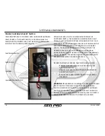
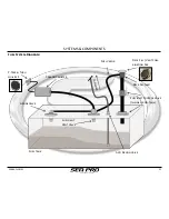
Diurnal Vapor and Emission Control Integrated
Fuel System Performance:
Normal Fuel Filling Event:
the fuel nozzle is inserted into the Fuel Inlet, and as fuel
begins to enter the tank, there will be a slight immediate
increase of tank pressure that is managed as the Fuel
Limit Vent Valve vents air and fuel vapors;
through the Carbon Canister and ultimately out
through the P
-
Trap
and the through the fuel Vapor & Fresh Air Vent
line and out through the vent in the Fuel Cap
When the fuel level reaches the Fuel Limit Vent Valve
Sensor, at a pre
-
determined safe level, the valve closes
and halts the exiting air and fuel vapors. This causes an
immediate increase in pressure that triggers the Inlet
Control Valve to close, stopping the flow of fuel into the
tank. When the Inlet Control Valve closes, the fuel fills
the inlet line, reaching the filling nozzle. The fill nozzle
will turn off and the fuel flow will stop when the tank is
full and prior to fuel spitting back out of the deck fill.
After the filling event is complete, the pressure will
gradually decrease inside of the tank, the Inlet Control
Valve will open, and the balance of the fuel in the inlet
line will be released into the tank.
Diurnal Emission Control:
When the ambient temperature increases, fuel expansion
occurs and vapor pressure increases. The Fuel Limit Vent
Valve will allow the emissions to escape through the
Carbon Canister, which scrubs and cleans the fuel vapor
of the harmful hydrocarbons, and releases it through
the P
-
Trap.
If the tank is filled to the level that causes the Fuel Limit
Vent Valve to close, the Grade Valve will allow the
emissions to travel the same path, through the Carbon
Canister and through the P
-
Trap.
When the ambient temperature decreases, the contents in
the fuel tank will condense. Fresh air is allowed to enter
through the P
-
Trap, the Carbon Canister, the Fuel Limit
Vent Valve and into the tank, allowing the system to
breath, stopping a potential vacuum effect.
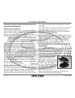
Over Pressurization or Prolonged Inclination of
the Fuel Tank:
Due to extreme temperature fluctuations, or a prolonged
period of inclination, the fuel level of vapor pressure
could cause both the Fuel Limit Vent Valve and the Grade
Valve to close, halting the normal vapor escape. Pressure
will continue to build inside of
the tank, and will build above
the Fuel Inlet Control Valve.
This creates a potentially unsafe
environment. To alleviate this
situation, there are sensors
built into the Deck Fill Cap that
will open the vent valve inside
of the Deck Inlet, releasing the
pressure and relieving the
system. Once the cause is corrected, the system will
return to the normal venting operation.
SYSTEMS & COMPONENTS
Summary of Contents for 248
Page 1: ...Owner s Manual and Quick Reference Guide 2017 WWW SEAPROMFG COM 248BAYSERIES ...
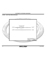
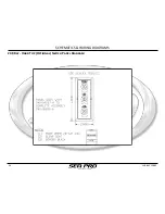
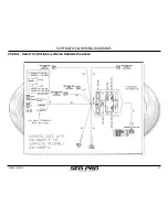
Page 39: ...248 BAY SERIES 39 SCHEMATICS WIRING DIAGRAMS 248 Bay Deck Wiring Harness Diagram ...
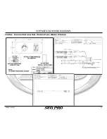
Page 40: ...40 248 BAY SERIES SCHEMATICS WIRING DIAGRAMS 248 Bay Hull Wiring Harness Diagram ...
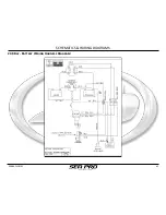
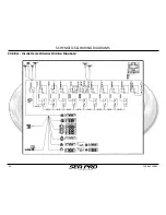
Page 41: ...248 BAY SERIES 41 SCHEMATICS WIRING DIAGRAMS 248 Bay Battery Wiring Harness Diagram ...
Page 42: ...42 248 BAY SERIES SCHEMATICS WIRING DIAGRAMS 248 Bay Amp Power Wiring Diagram ...
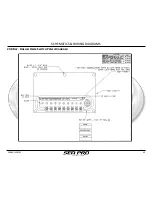
Page 43: ...248 BAY SERIES 43 SCHEMATICS WIRING DIAGRAMS 248 Bay Dash Helm Switch Panel Diagram ...
Page 44: ...44 248 BAY SERIES SCHEMATICS WIRING DIAGRAMS 248 Bay Inside Helm Console Wiring Diagram ...
Page 46: ...46 248 BAY SERIES SCHEMATICS WIRING DIAGRAMS 248 Bay Hard Top Optional Switch Panel Diagram ...
Page 47: ...248 BAY SERIES 47 SCHEMATICS WIRING DIAGRAMS 248 Bay Hard Top Optional Wiring Harness Diagram ...